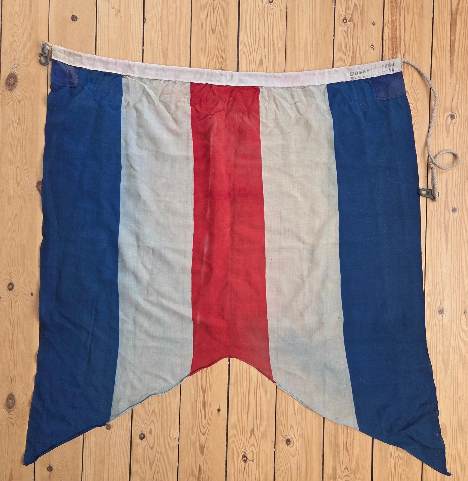
FG-047
C-Doppelstander
Germany · Allied occupation
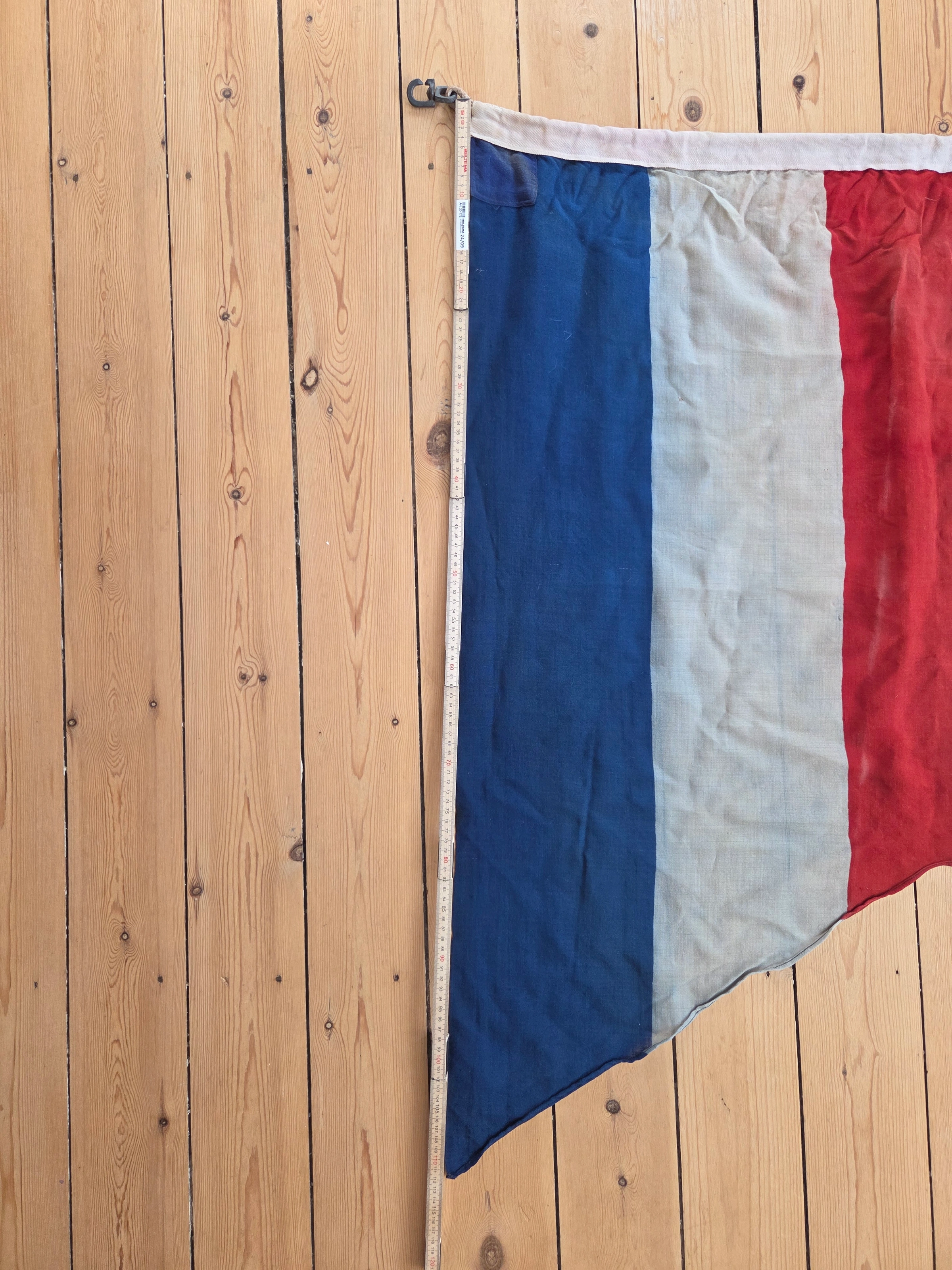
93 × 112 cm
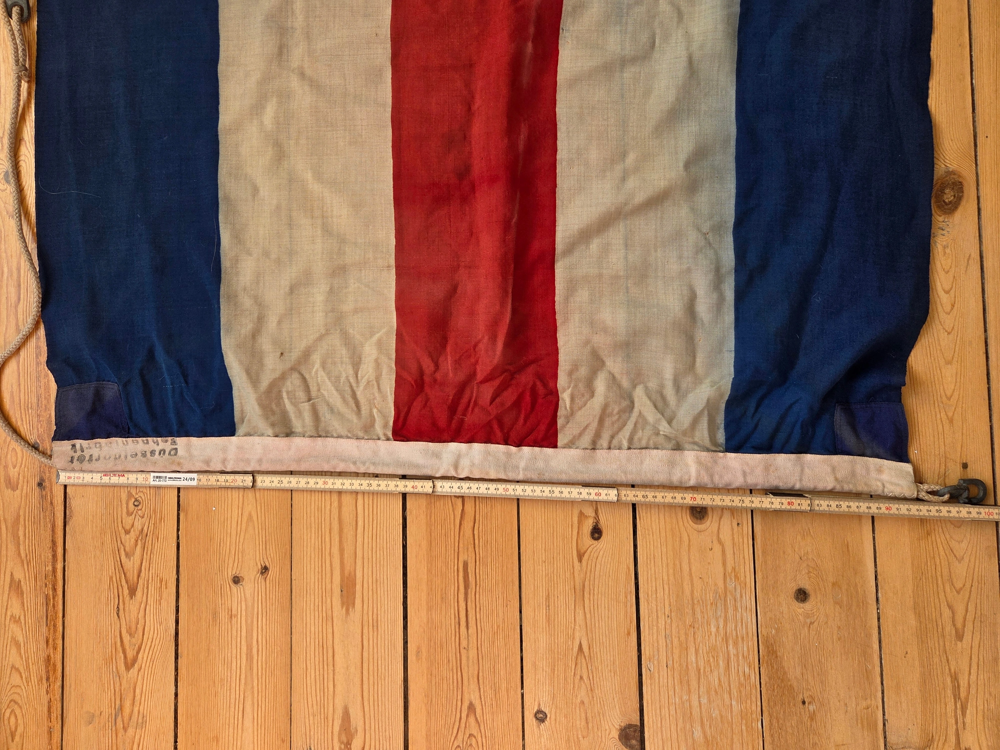
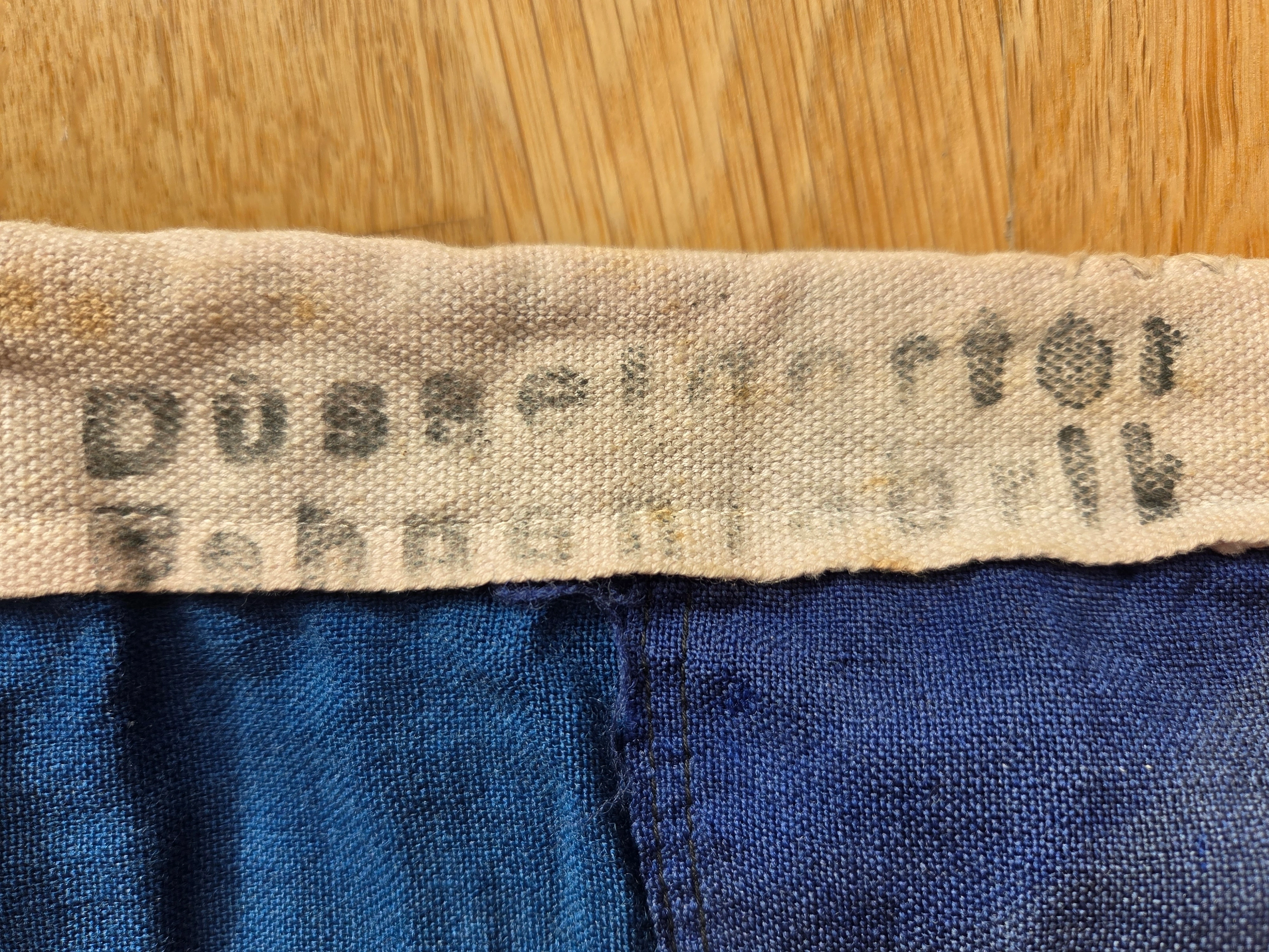
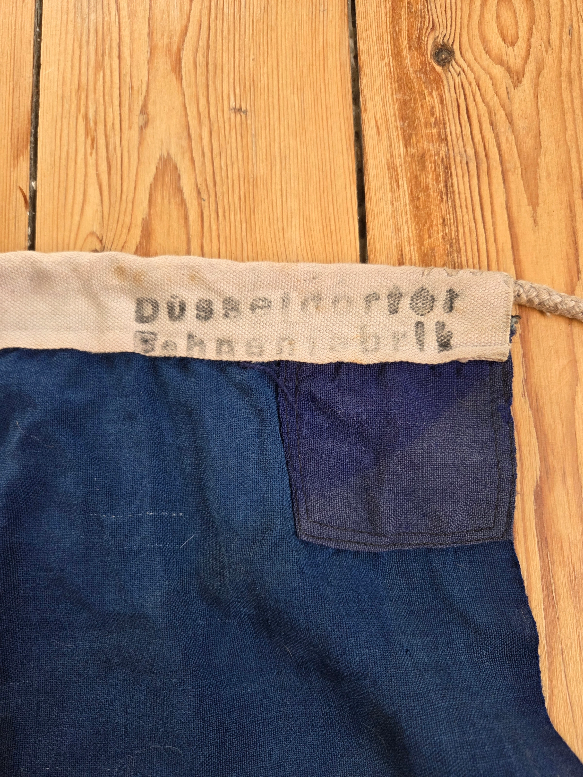
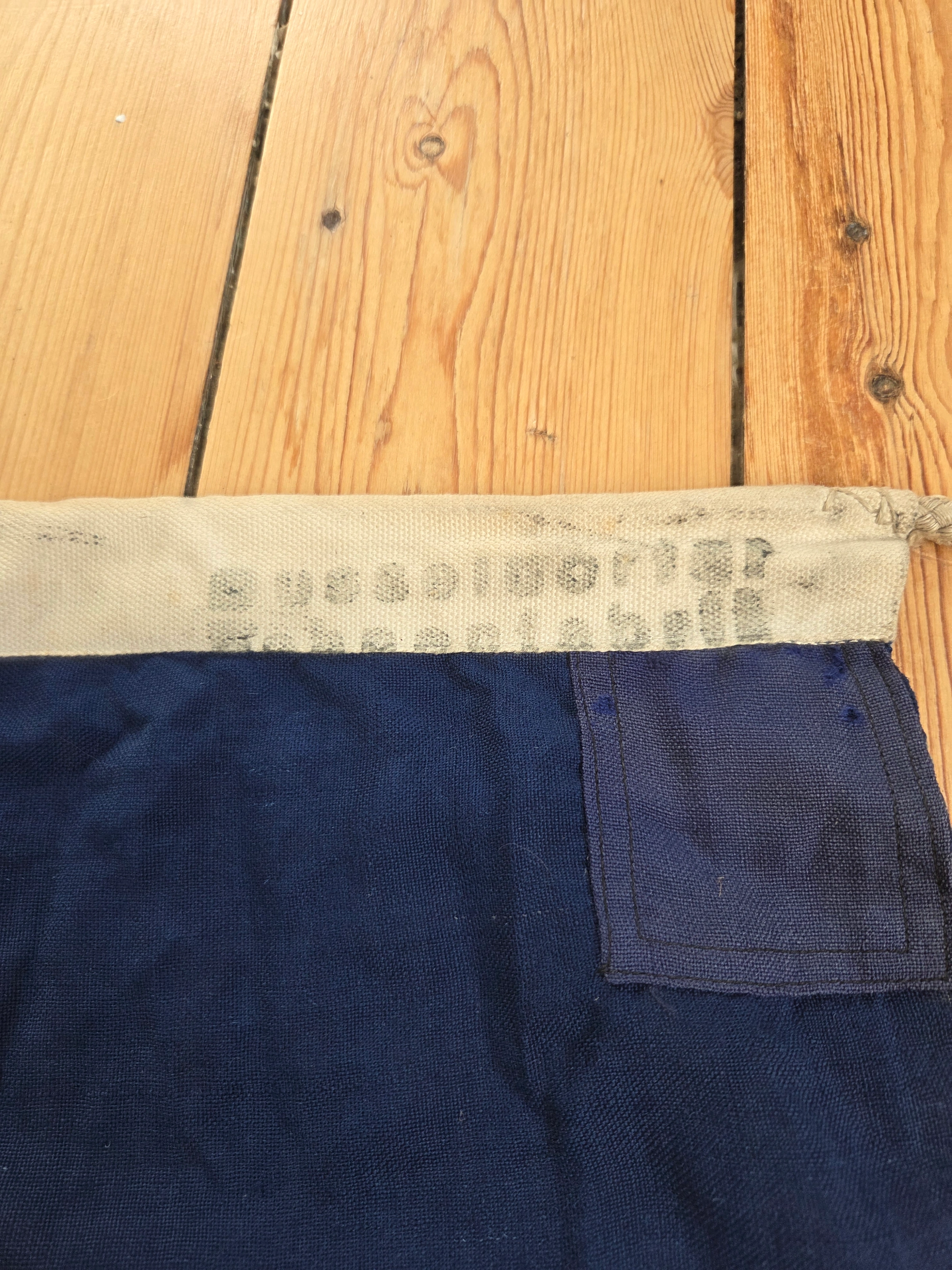
Markings: Düsseldorfer Fahnenfabrik maker stamp (source attribution)
Germany / Merchant ensign · C-Doppelstander
Erkennungsflagge deutscher Handelsschiffe
Research into the German occupation ensign, its regulations, construction and surviving examples, including collection specimens FG-047 and FG-048.
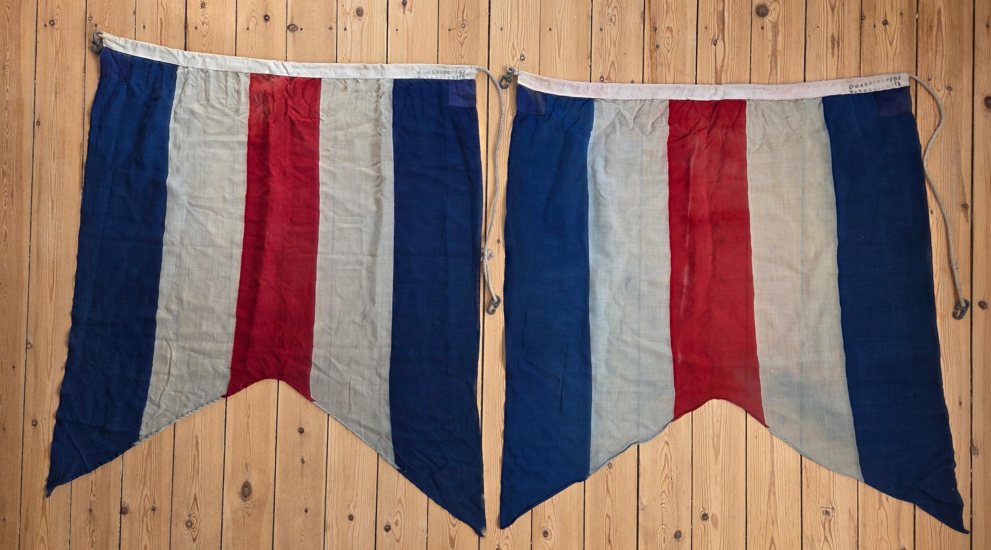
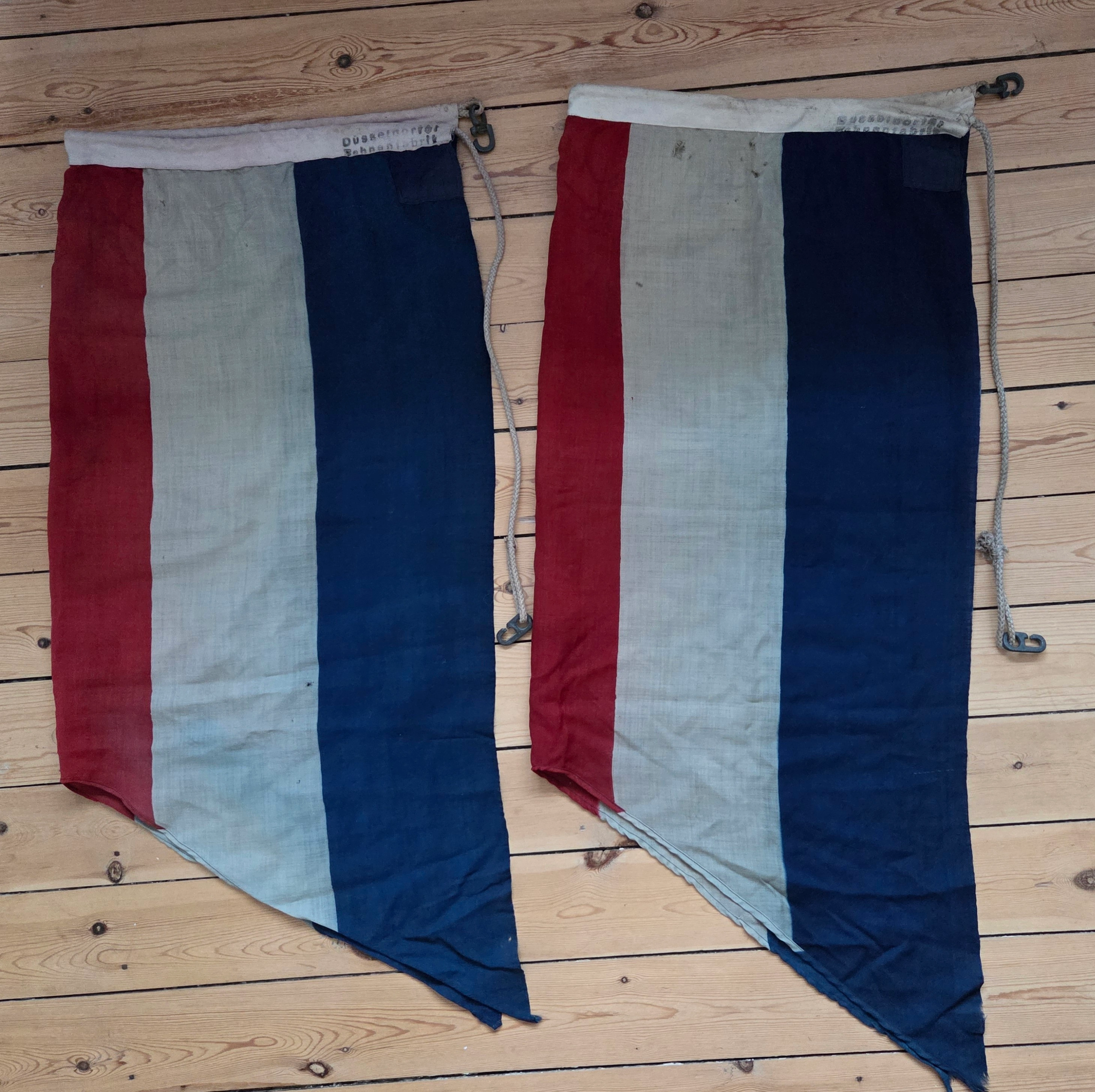
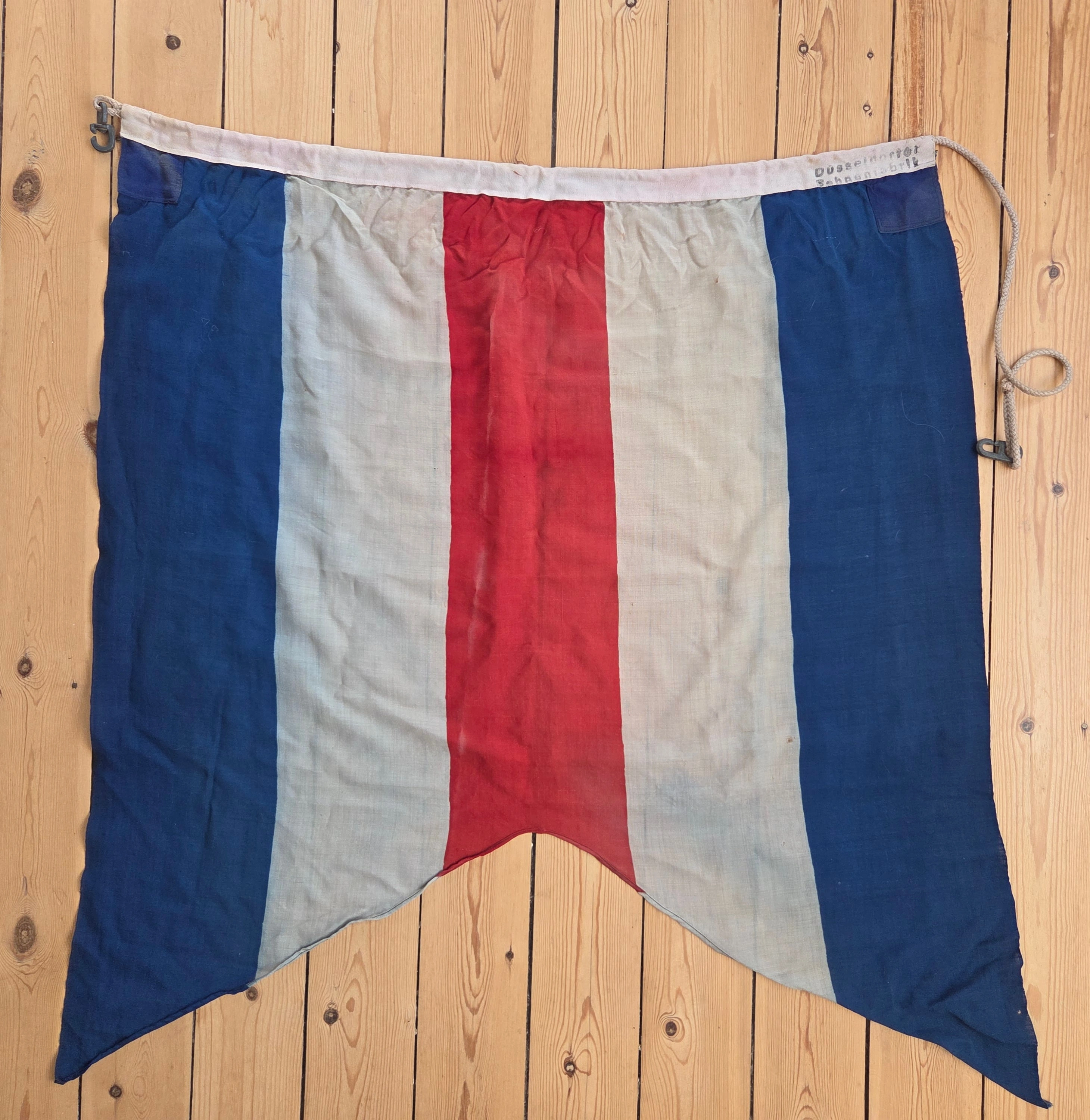
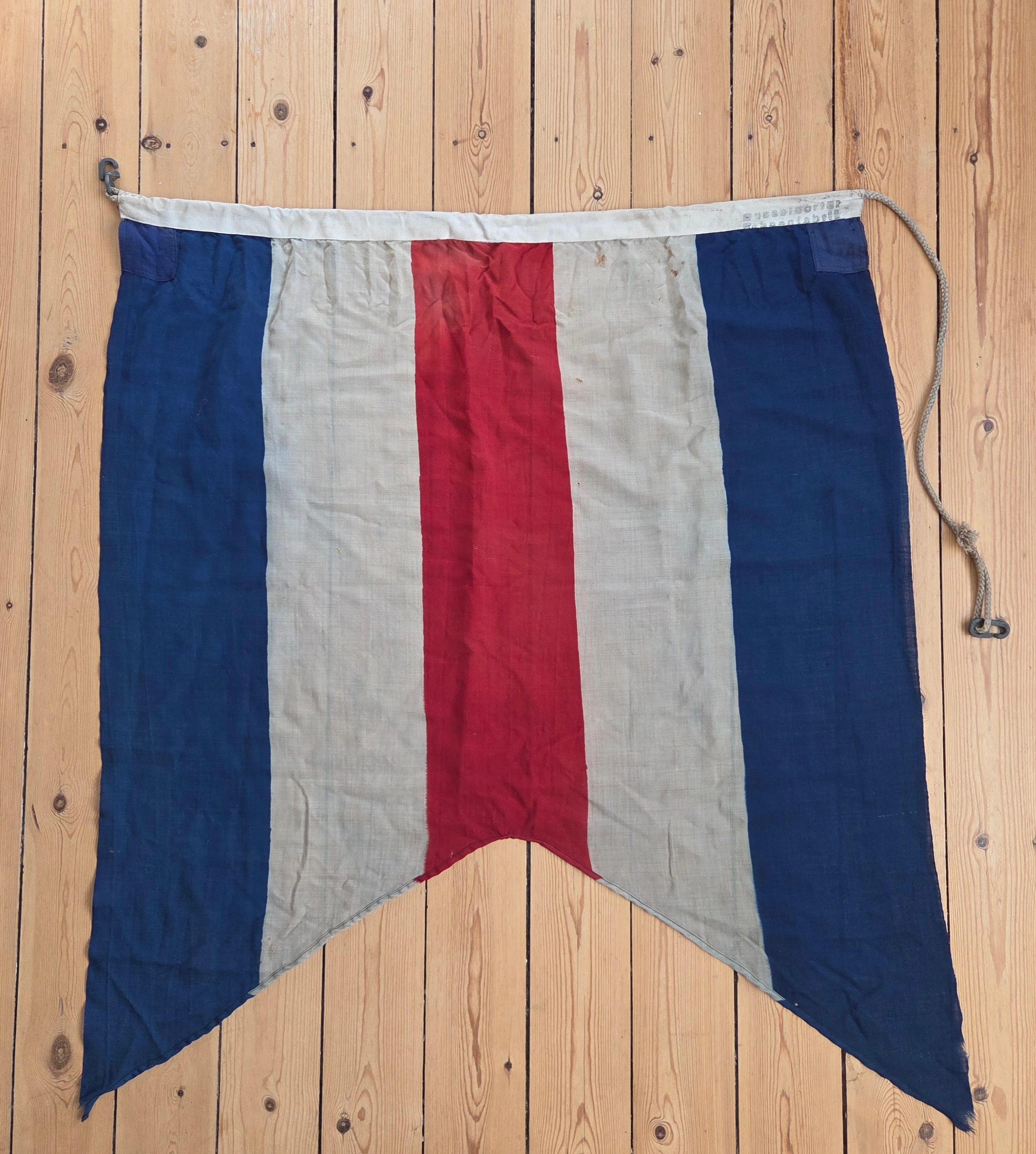
FG-047
Germany · Allied occupation
93 × 112 cm
Markings: Düsseldorfer Fahnenfabrik maker stamp (source attribution)
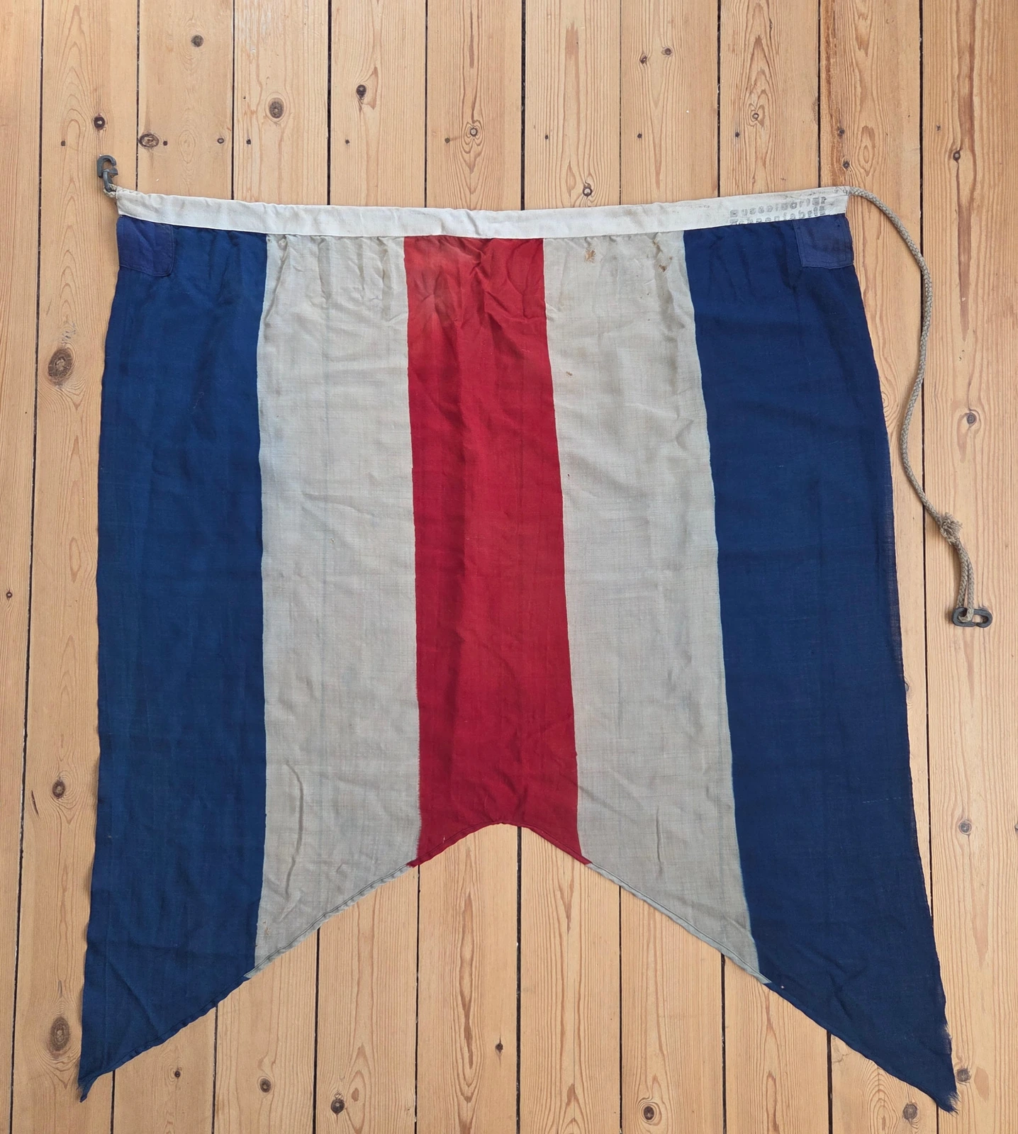
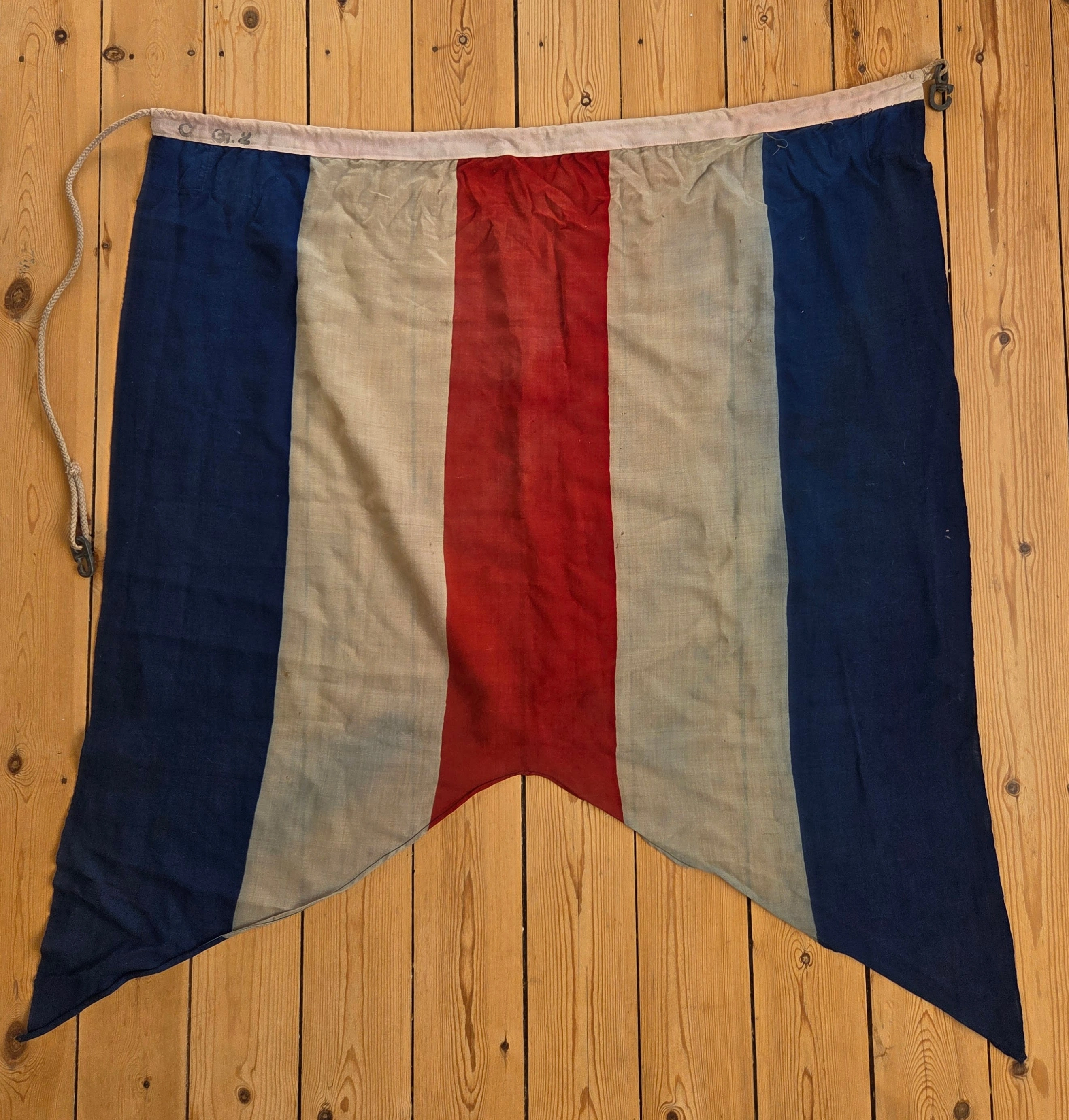
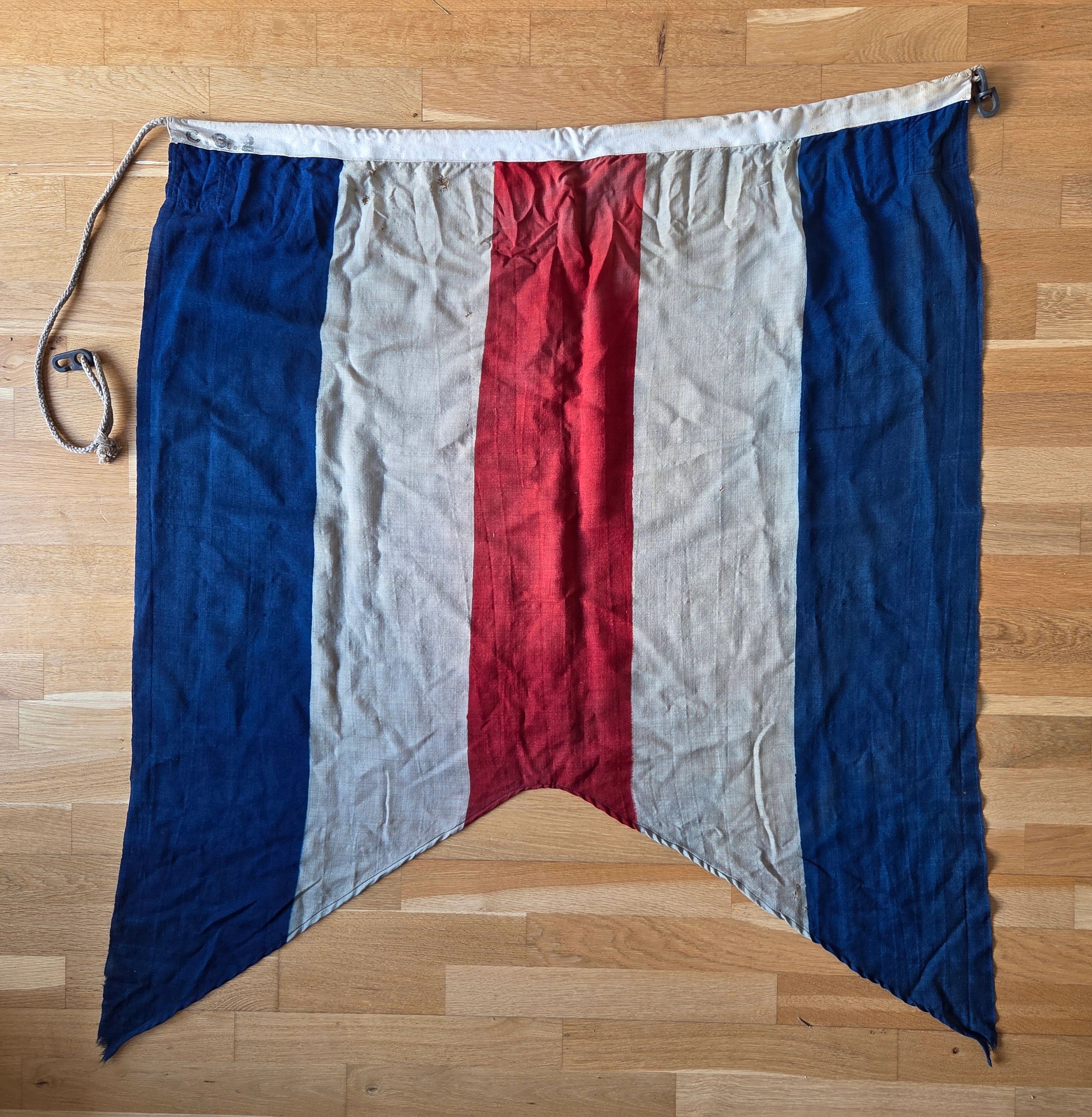
FG-048
Germany · Allied occupation
96 × 115 cm
Markings: Düsseldorfer Fahnenfabrik maker stamp (source attribution)
Flag ID: FG-047 & FG-048
After the German capitulation in May 1945, all national insignia were banned, and German merchant vessels were ordered to operate under Allied control. One of the most obscure results of this policy was the C-Doppelstander — a modified version of the International Signal Flag “C” used as a temporary ensign for German shipping until 1951. Despite its importance in the early post-war period, very few examples survive, and its exact proportions, construction details, and historical rationale remain poorly understood.
This study brings together six independent references — including two maker-stamped cloth examples, archival photographs, a museum piece, and period film footage — to reconstruct how the flag was made, how it was used, and why the Allies chose this particular design.
The study asks four practical questions about the C-Doppelstander (the Allied occupation ensign used by German merchant shipping after 1945):
We build the case from six independent reference points:
Across these references we test two linked hypotheses: first, that workshops and crews reused signal C stock (≈ 5:6 family) rather than manufacturing a new rectangular standard (e.g., 2:3 or 3:5); second, that the swallowtail was cut to a broad, practical wedge (≈ 106–110°) rather what is shown in Annex A to Allied Control Council Law No. 39.
Online summaries often assume neat 2:3 or 3:5 rectangles. Our cloth, photos, and film suggest a different, signal-driven reality. By anchoring the study in six independent references and the tests we run on them, we show the physical standard actually used at sea and the operational reasoning behind choosing “C” (and later “D”/“E”).
All six anchors converge on a signal-flag body (≈ 5:6) with a broad, traditional swallowtail cut; our two maker-stamped flags present as period, working originals. The detailed evidence and caveats follow in Sections 3–9.
Designation: C-Doppelstander (Erkennungsflagge deutscher Handelsschiffe)
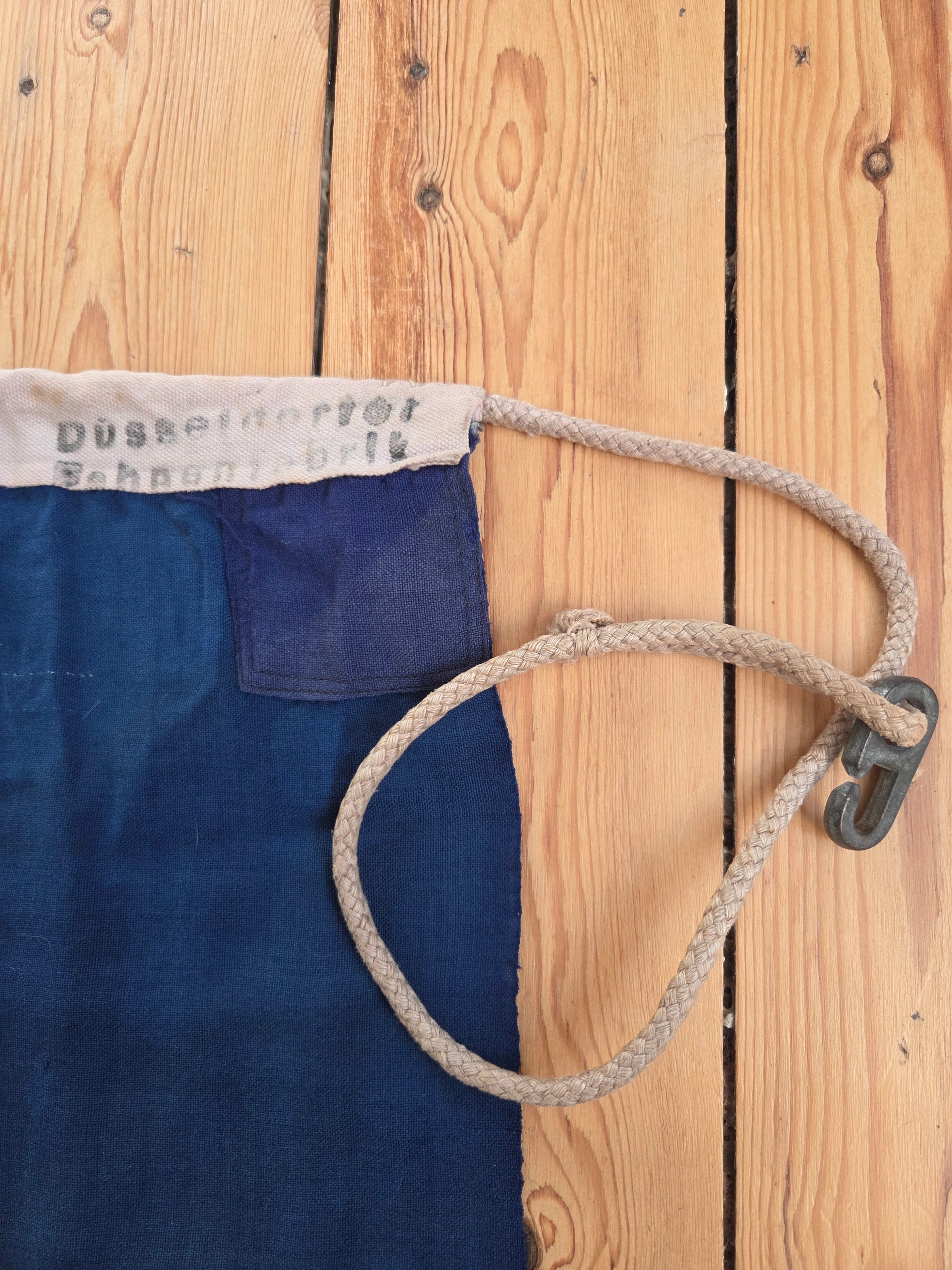
Maker’s stamp on both hoists identifies Düsseldorfer Fahnenfabrik (DFF). The workshop’s continuity into the early 1950s is set out in Section 8, providing the archival basis for this attribution.
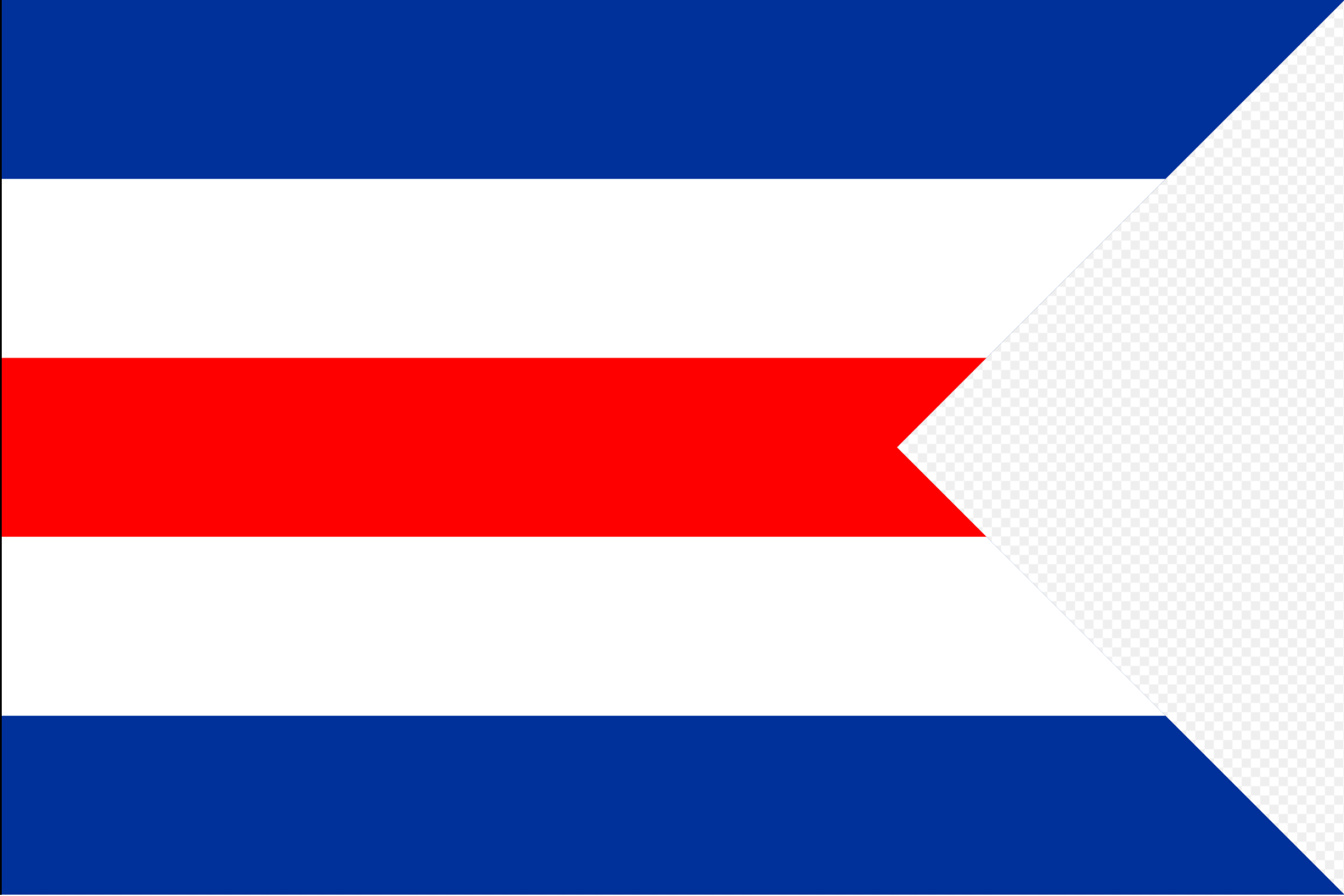
After the German capitulation of 7–8 May 1945, Reich flags were banned as part of denazification, and German shipping operated only under Allied control. An Allied war diary entry of 9 May 1945 directed German war and merchant vessels “to fly at the peak International Code Flag C with a triangle cut from the fly thus transforming it into a burgee.” War Diary, 9 May 1945 (p. 215). This provided a provisional identification ensign under Allied supervision, not a formally standardised flag.
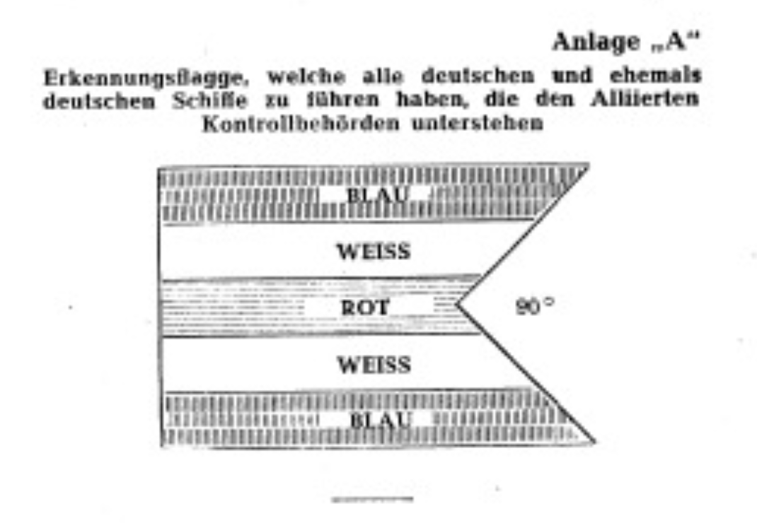
It was only with Allied Control Council Law No. 39 (issued 12 Nov 1946, effective 17 Jan 1947) that the C-Doppelstander was codified in regulation as the official German merchant ensign. The law’s Annex A shows only a schematic sketch—“C” plus a 90° cut—without dimensions or ratios (see Section 6). Any numerical reconstructions of proportions must therefore be regarded as approximate.
In practice, however, the flag’s operational life was limited. With the Basic Law of 23 May 1949, black-red-gold was constitutionally recognised as the flag of the Federal Republic. From that point, German shipping had no incentive to continue with the C-Doppelstander. The ensign remained in formal regulations until 1951, but its effective service life was essentially 1945 – 1949.
Open question: while the purpose and duration of the C-Doppelstander are well documented, its selection remains puzzling. Why the letter “C” — and not another signal flag? No Allied record explains this, yet the same pattern later reappeared in the D- and E-occupation flags of the Ryukyu Islands and Japan. This recurring logic suggests the choice was neither random nor symbolic, but rooted in Allied signal practice. Section 3a therefore explores the earliest known uses of signal flag C and the possible rationale behind its adoption as an occupation ensign.
This synthesis outlines the working hypothesis for why the International Code flag “C” (Charlie) was selected for use on German vessels after May 1945 and how it later evolved into the broader Allied occupation-flag system. The evidence below remains under review pending final archival confirmation.
The Allied order of 9 May 1945 instructed all German and ex-German ships “to fly at the peak International Code Flag C with a triangle cut from the fly.” No reason for choosing the letter C was recorded, yet several operational and historical factors suggest the decision followed established signalling logic rather than improvisation.
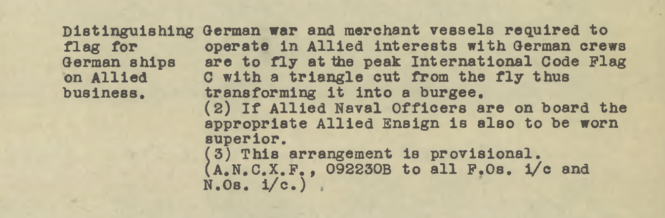
Practical availability and adaptation. Before the war, all internationally trading German merchant ships were required to carry full sets of International Code of Signals flags from suppliers such as DFF and Schreiber. During the war, most of the fleet was militarised under the Reichskommissariat für Seeschifffahrt and operated under the Flaggenbuch 1939 system used by the Kriegsmarine. By May 1945, only a few civilian vessels still carried ICS sets, yet this was enough to make the Allied order immediately practicable — crews could simply cut the fly of an existing C flag. In surrendered ports such as Kiel, Flensburg, and Bremerhaven, Allied Control Officers likely authorised or issued replacement ensigns and signal flags for cleared German vessels — a process described in surviving British Naval Control Service correspondence (British Library, Add. MS 71786 ff., 1946–47). Licensed German workshops soon resumed production under supervision, as indicated by surviving Düsseldorfer Fahnenfabrik stamps. The preserved DFF-marked C-Doppelstander examples therefore represent the formalised post-surrender production phase — directly evolved from the 1945 field practice.
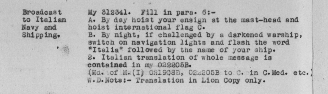
So, as the C flag had already served a signalling role in 1943 and carried neutral connotations, it made perfect sense in 1945 simply to cut the fly into a swallowtail and repurpose it as a temporary ensign for German shipping.
A similar progression unfolded in the Pacific. Just as the C-Doppelstander began as an improvised measure in May 1945, the same logic resurfaced with the D-pennant in the Ryukyu Islands and the E-pennant in Japan.
Following the Battle of Okinawa (March – June 1945), Admiral Chester Nimitz issued Proclamation No. 1 (5 April 1945), establishing the U.S. Naval Government of the Ryukyus — meaning the area was already under Allied naval control by the time the battle ended in June. On 18 July 1945, administrative authority was briefly transferred from the Navy to the U.S. Army Forces in the Pacific (AFPAC), but naval command was restored on 21 September 1945 with the creation of the U.S. Military Government of the Ryukyu Islands. Japanese symbols were prohibited, and civilian ships were not permitted to fly the U.S. flag. Operational evidence suggests that the D-pennant was already introduced locally following Okinawa’s capture to mark Allied-controlled shipping during this transition period. This timing explains the alphabetical sequence: with “C” assigned to Germany, “D” naturally followed as the next identifier once operations shifted west toward Japan.
Japan’s Diplomatic Bluebook 1967 notes that “Okinawan merchant ships adopted the ‘D’ pennant as a naval ensign immediately after the war; however, since it was not recognised, many vessels flying it were seized.” This confirms informal D-flag use before its formalisation under USCAR Ordinance No. 148 (1955), which defined the ‘Ryukyu vessel flag’ as a double-pointed derivative of the same pennant.
Taken together, the C-Doppelstander (Germany), D-pennant (Ryukyu Islands), and E-pennant (Japan) form what appears to be both an alphabetical and chronological sequence of Allied occupation ensigns — a deliberate continuation of a proven control-signal concept. Had further zones been designated, the next logical issue might indeed have been an “F” swallowtail.
Archival research is ongoing to confirm whether the C flag’s control meaning was codified in Allied signal directives (1944 – 45) and to establish the precise introduction dates of the D and E pennants.
Thousands must have been issued; very few survive. The duty window was short (essentially 1945–1949), the environment was harsh (salt, wind, spray), and after 1951 there was no souvenir market—many pieces were discarded or repurposed.
We conducted systematic, multilingual searches (German, English, Danish, Russian, Dutch, French, Polish, Spanish, Italian), including deliberately misleading keyword variants—e.g., “Signalflagge C,” “German flag 1945–1949,” “Doppelstander,” “double-stander,” and “Allied-occupation German flag.” Result: no public sales and almost no museum catalogue entries. When examples do surface, they are often mis-catalogued as ordinary signal flag C rather than the swallow-tailed C-Doppelstander ensign.
Requests to major maritime and historical museums yielded almost no surviving examples. However, the Haus der Geschichte in Bonn confirmed one preserved specimen (measured 114 × 97 cm), closely matching the Gr. 2 size class. Its existence provides a critical institutional reference alongside the privately held and published examples described below.
A rare published photo appears on page 5 of Thilo Biegler’s study Die Deutschen Kriegsmarineflaggen 1935–1945 (FIAV PDF), where the C-Doppelstander is shown as “Gr. 1 C” (fig. 2). His photo confirms the signal-flag origin and depicts a tail angle visibly wider than the schematic 90°, though no exact measurements are given.
Source: Thilo Biegler – Deutschen Kriegsmarine (PDF).
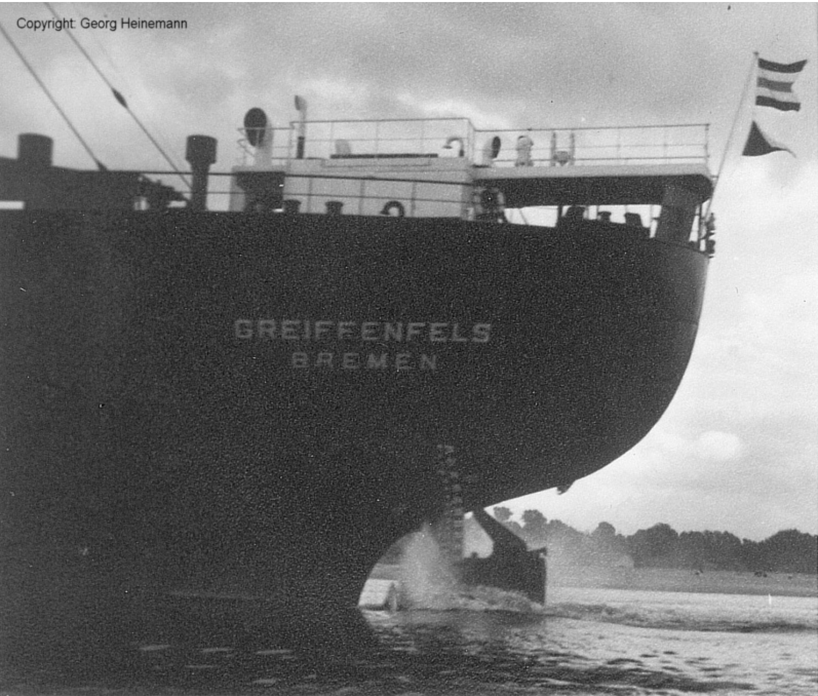
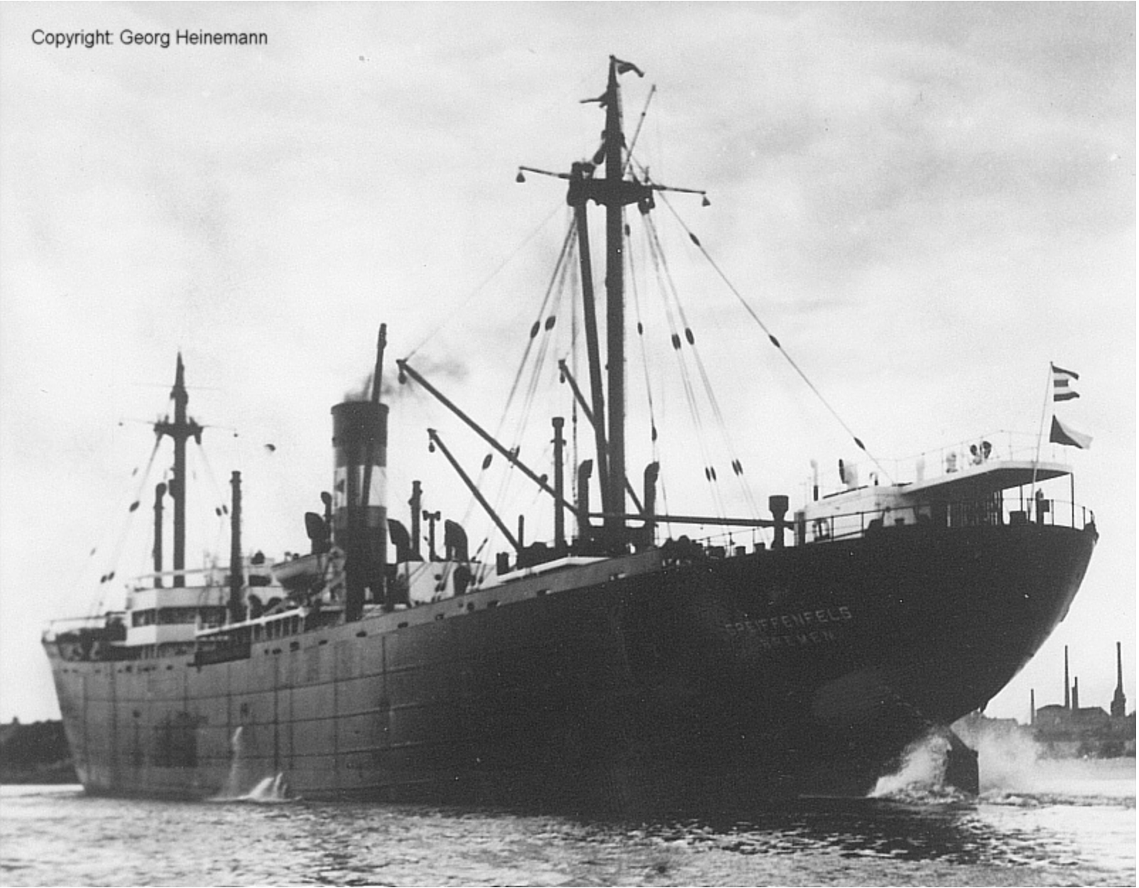
Two period photographs from the DDG Hansa archive show the cargo ship Greiffenfels flying the C-Doppelstander at the stern. The accompanying archive note states: “Als Nationalflagge wurde bis zum 23.02.1951 der Doppelstander ‘C’ gesetzt.” The photographs confirm the flag’s working use and proportions consistent with our measured pieces.
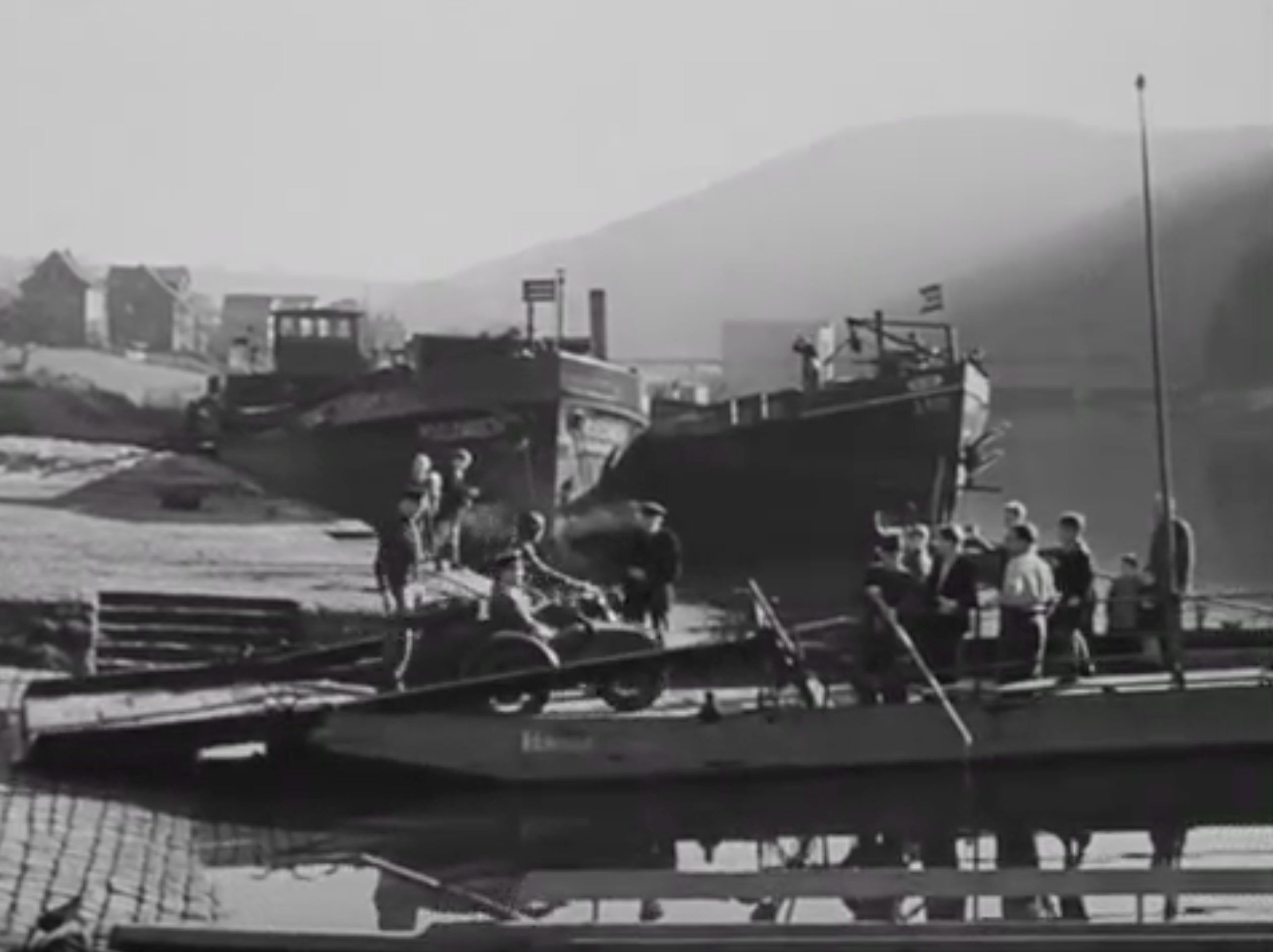
In addition, period film evidence further supports this: in the 1949 feature I Was a Male War Bride, a German vessel appears in the background flying the same swallow-tailed C ensign (timestamp 17:55). This provides the sixth independent confirmation of the flag’s form in actual post-war service.
Our two matching, maker-marked examples therefore form a high-confidence reference pair for this otherwise scarcely documented ensign type. For construction details, see Section 5; for measurements and ratio analysis, see Section 6.
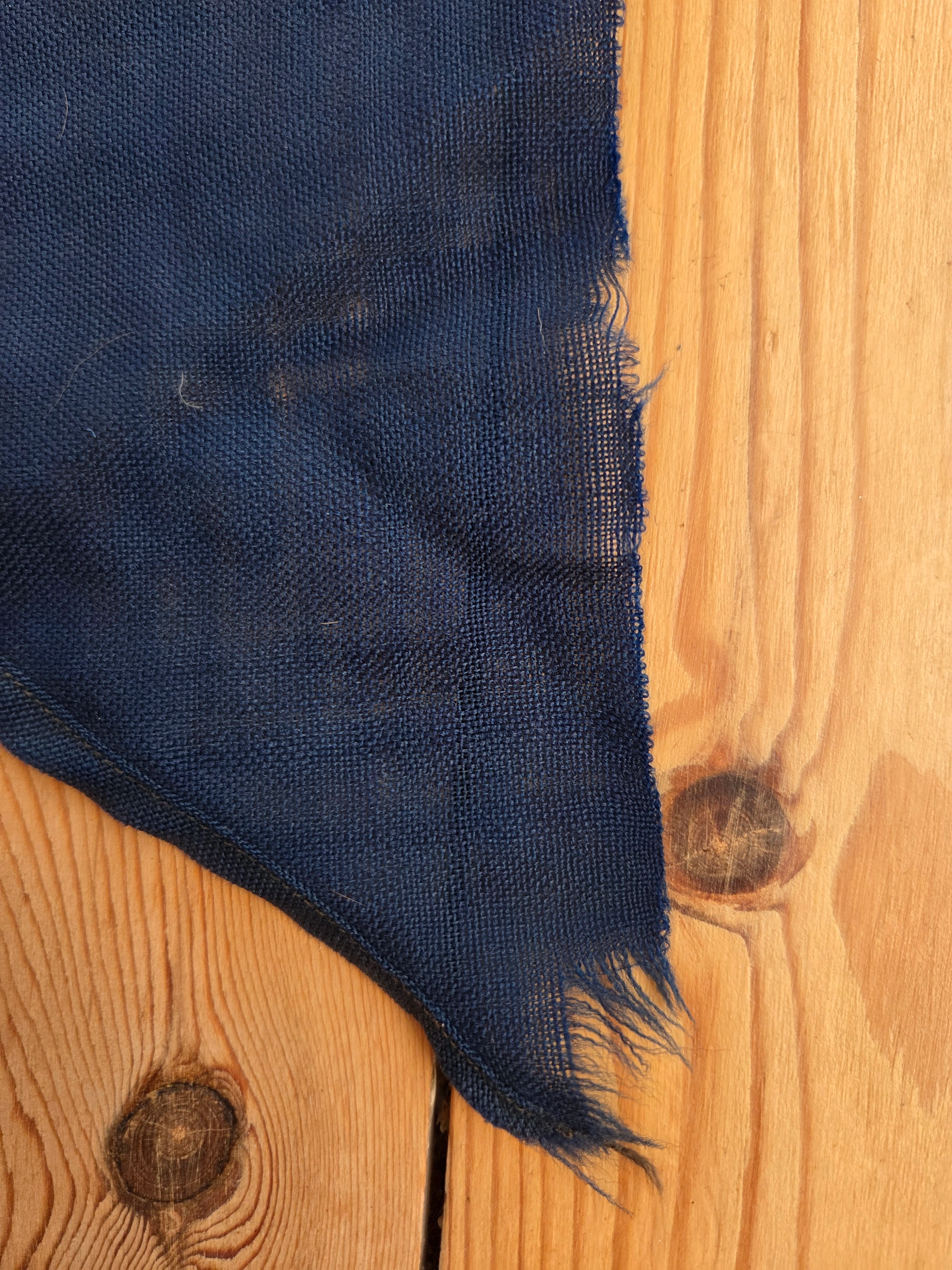
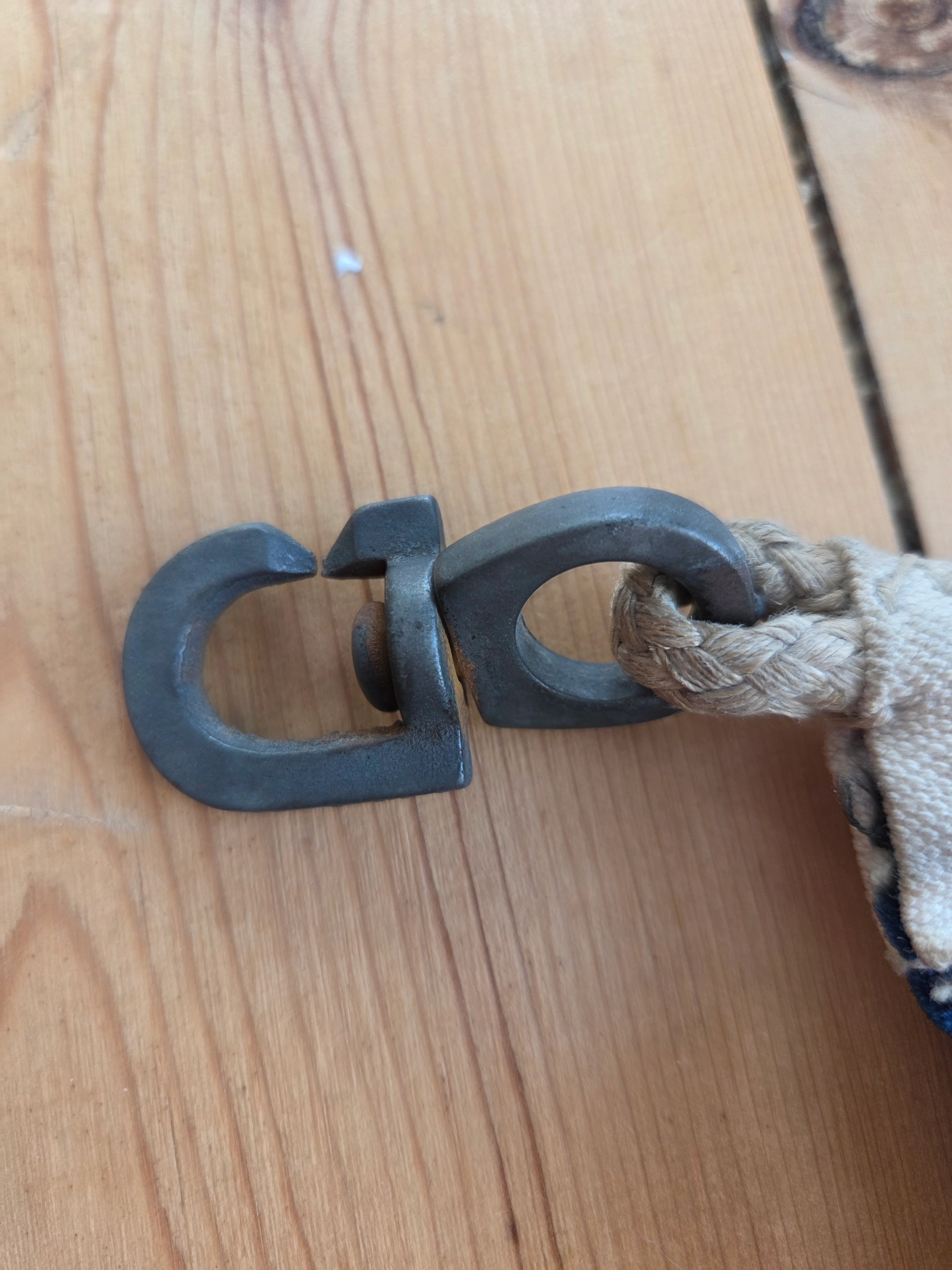
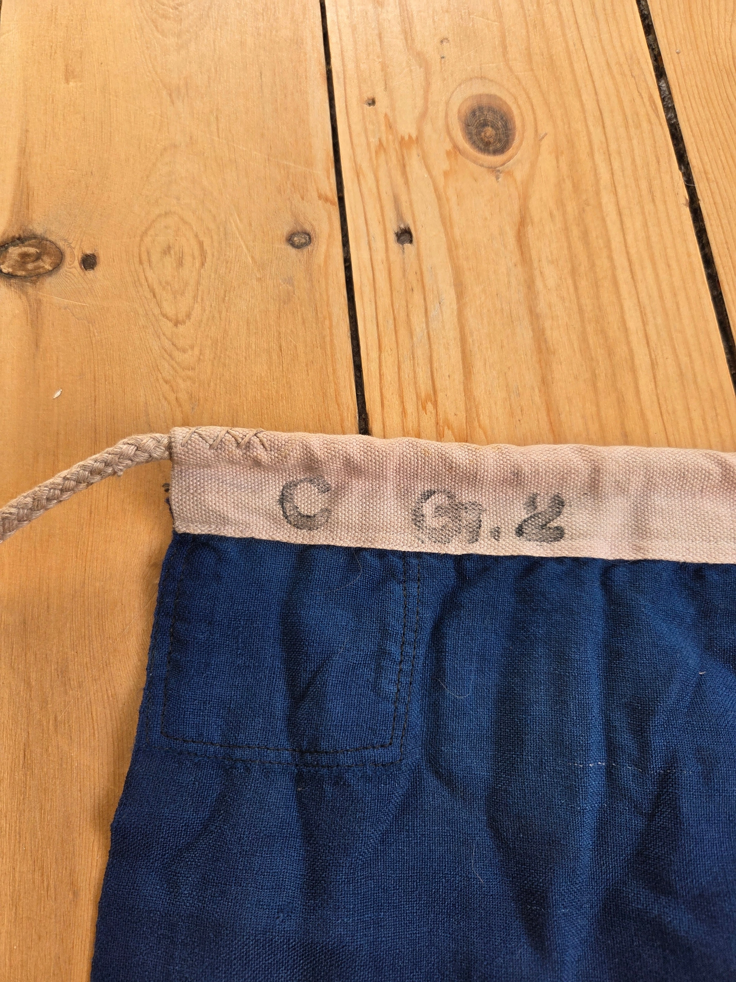
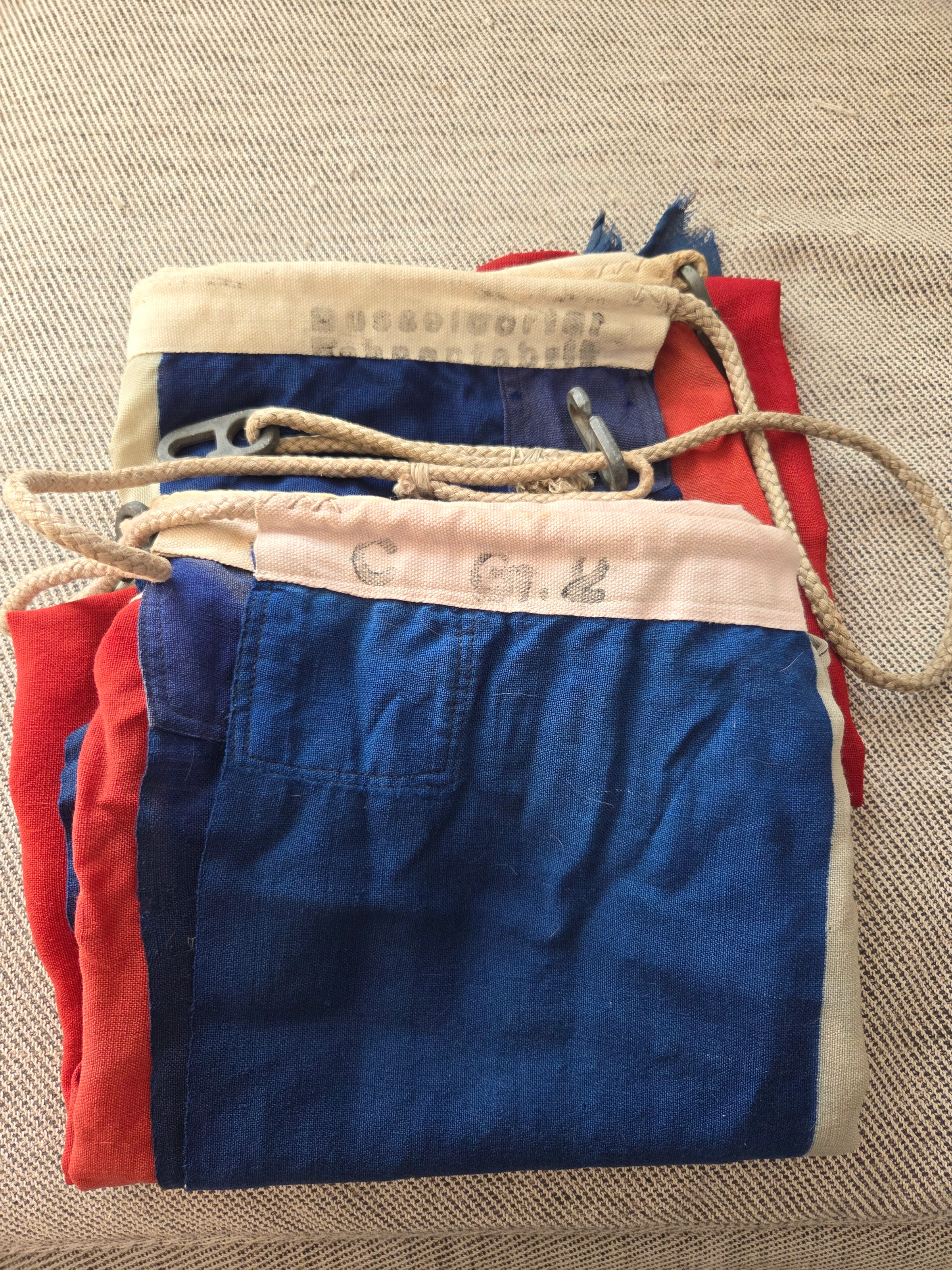
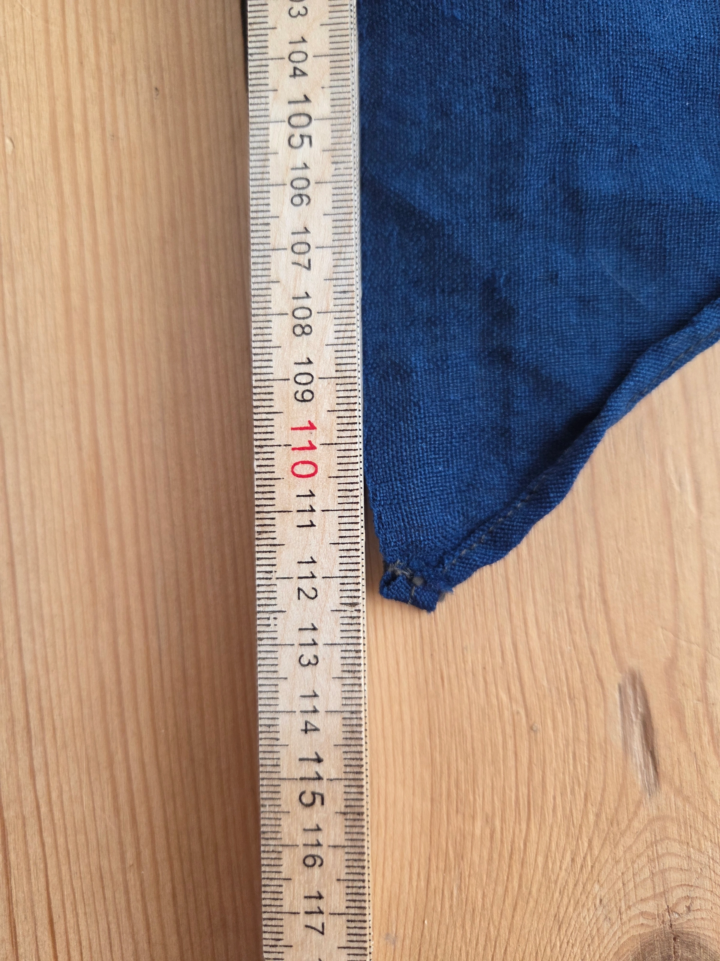
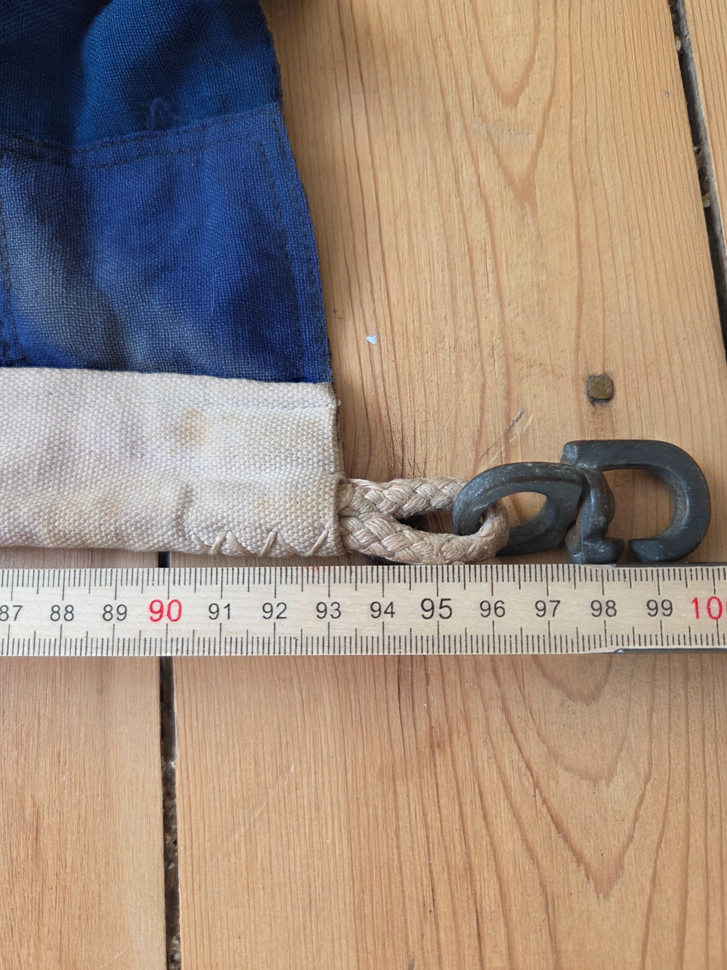
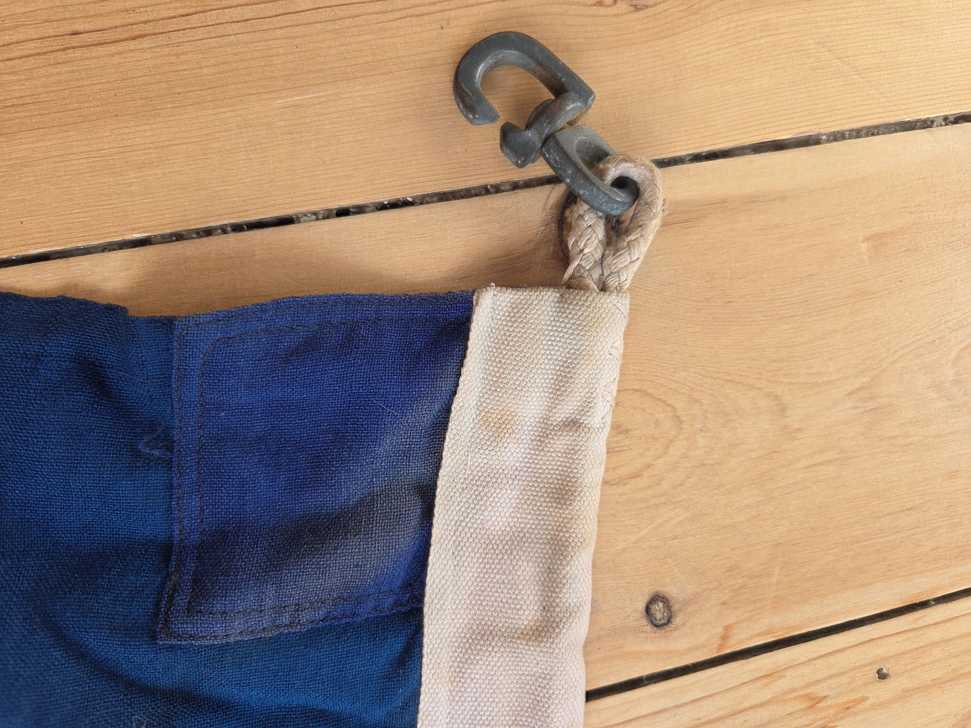
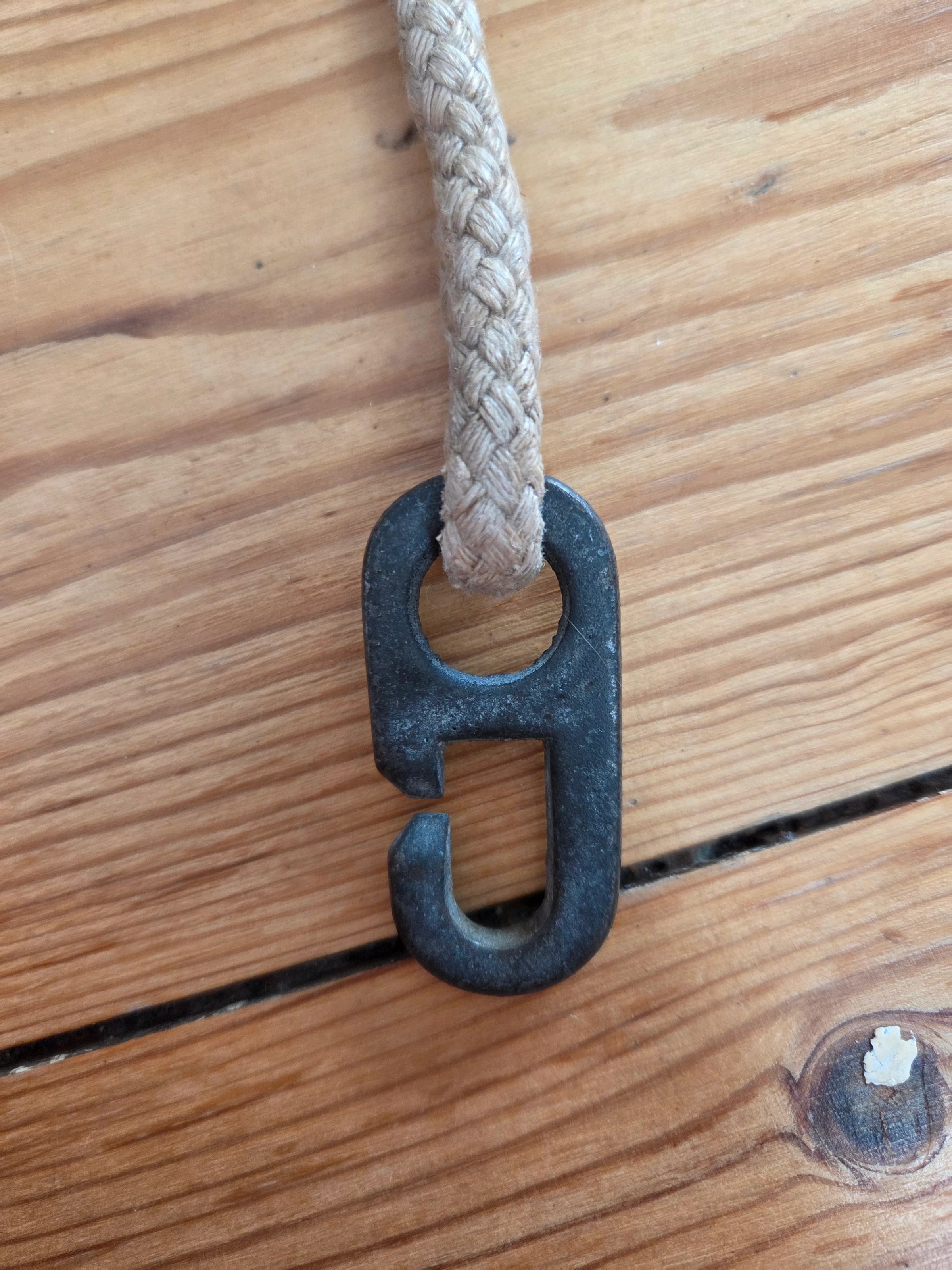
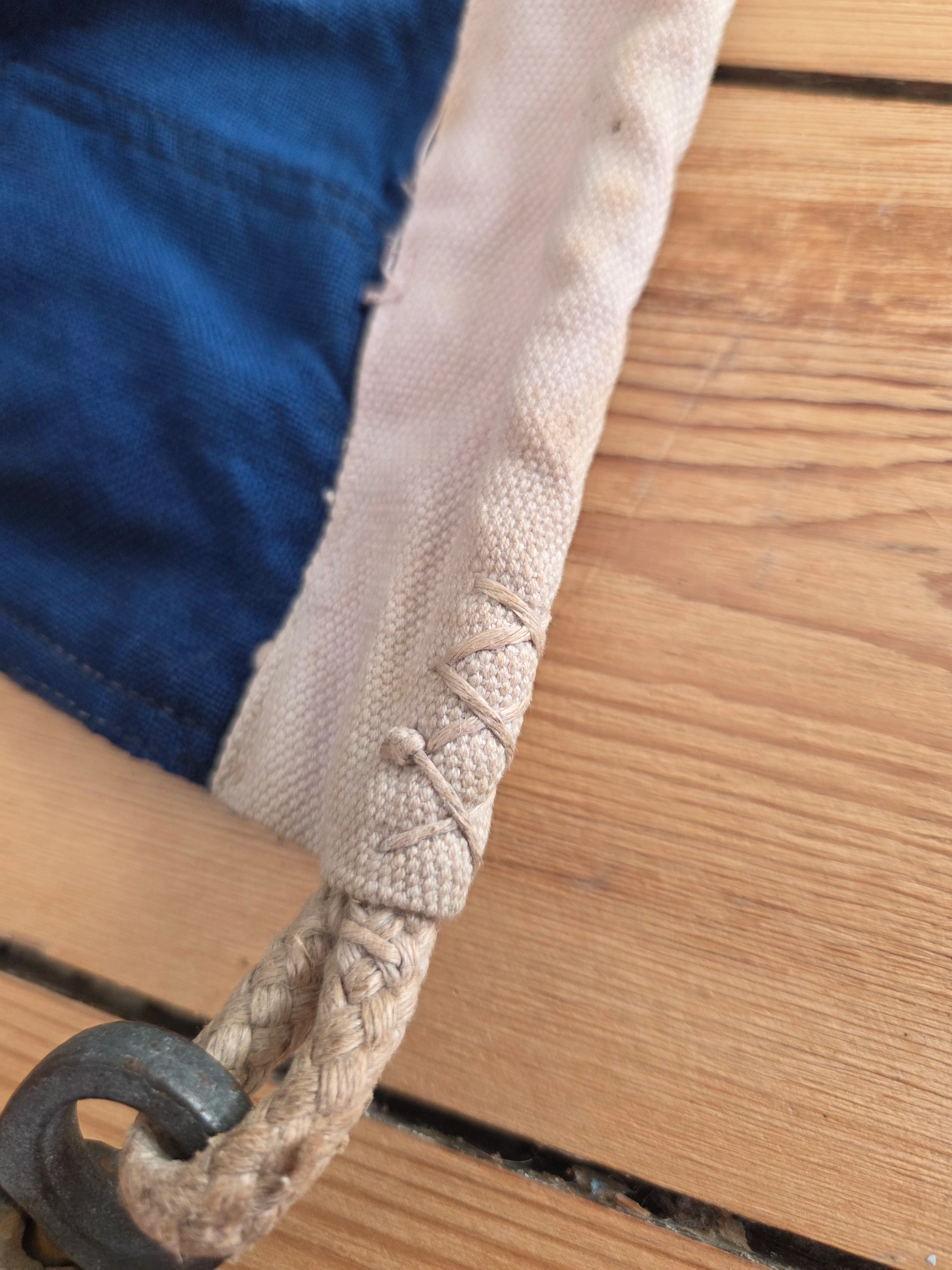
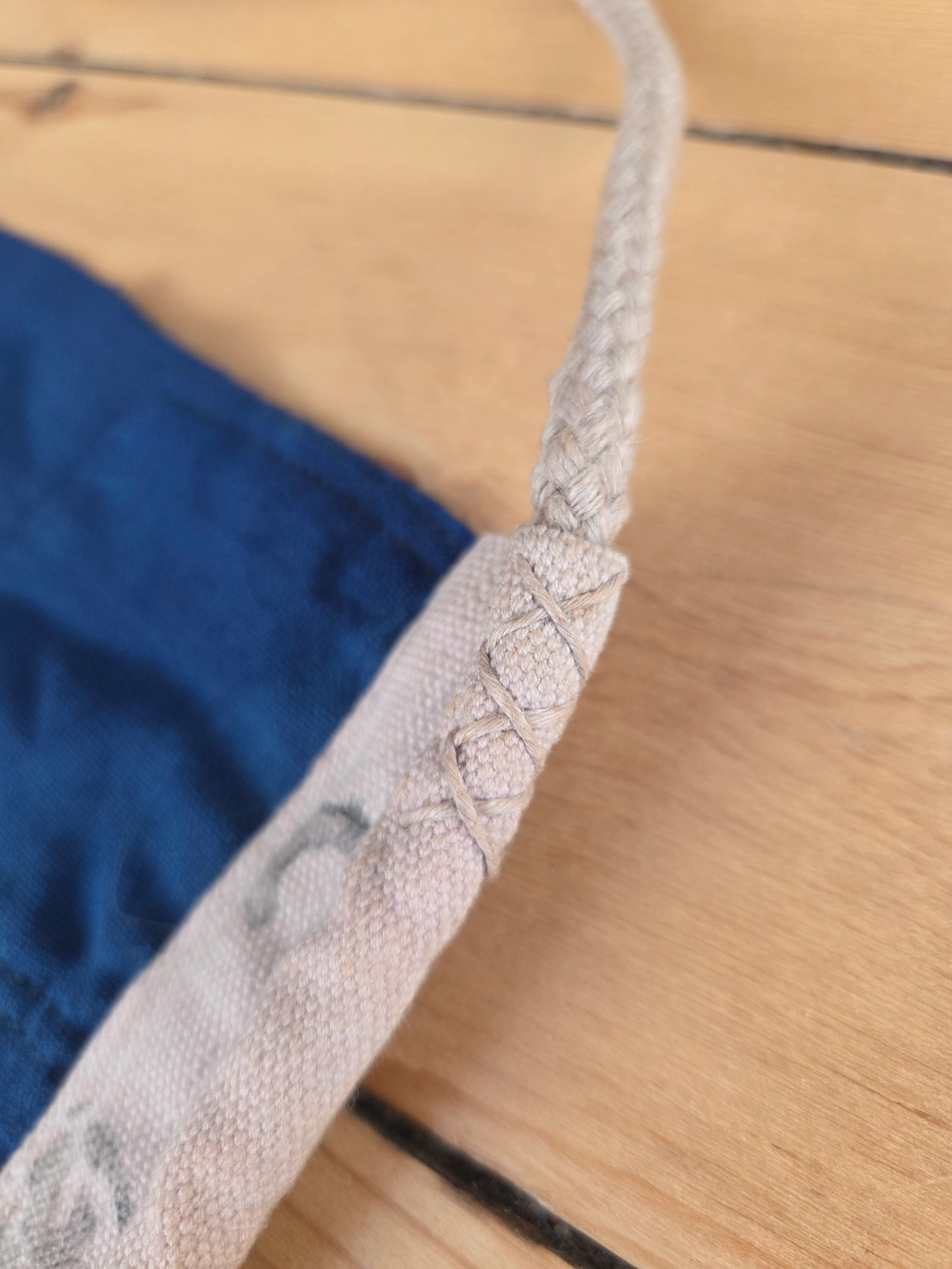
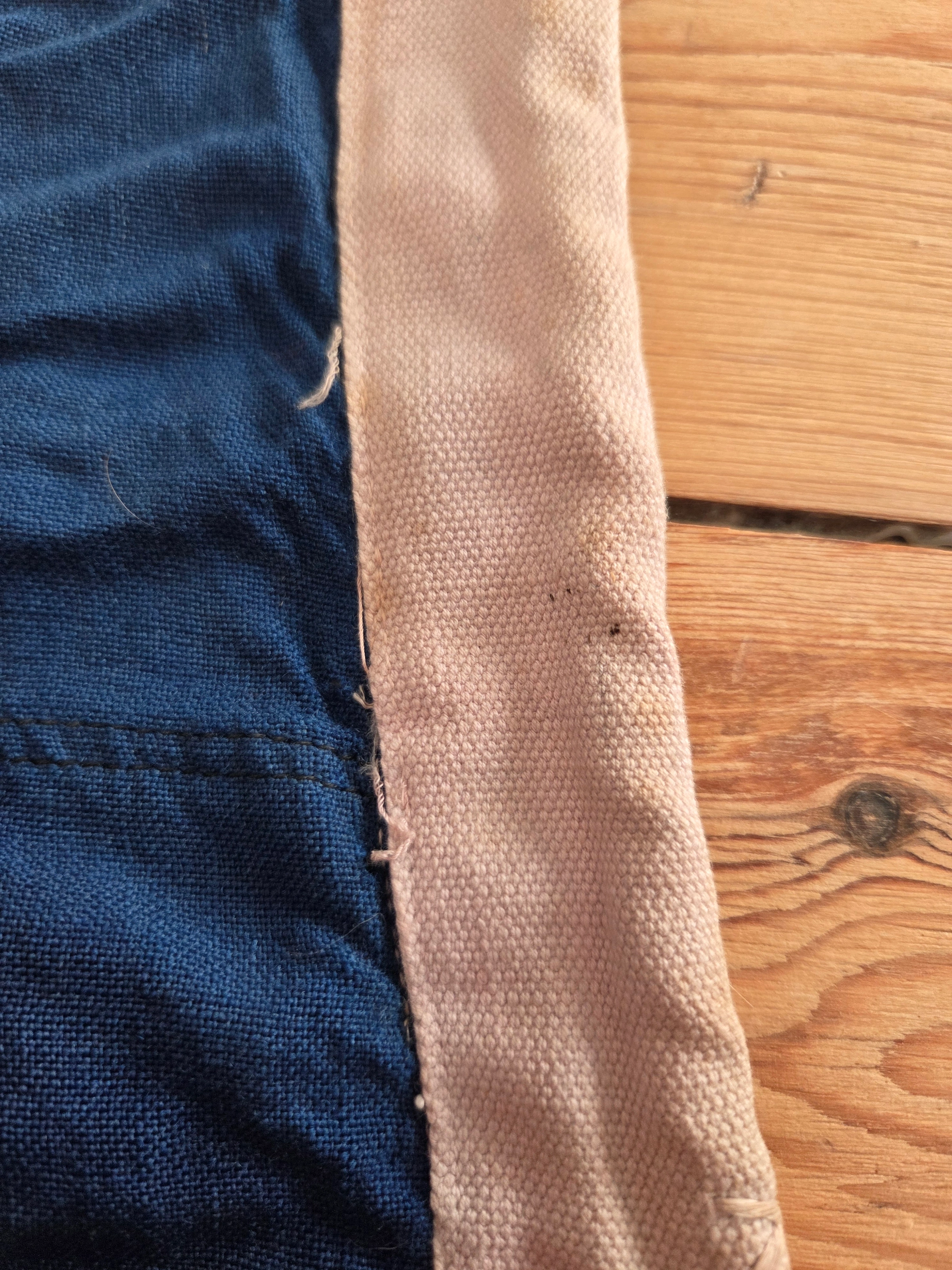
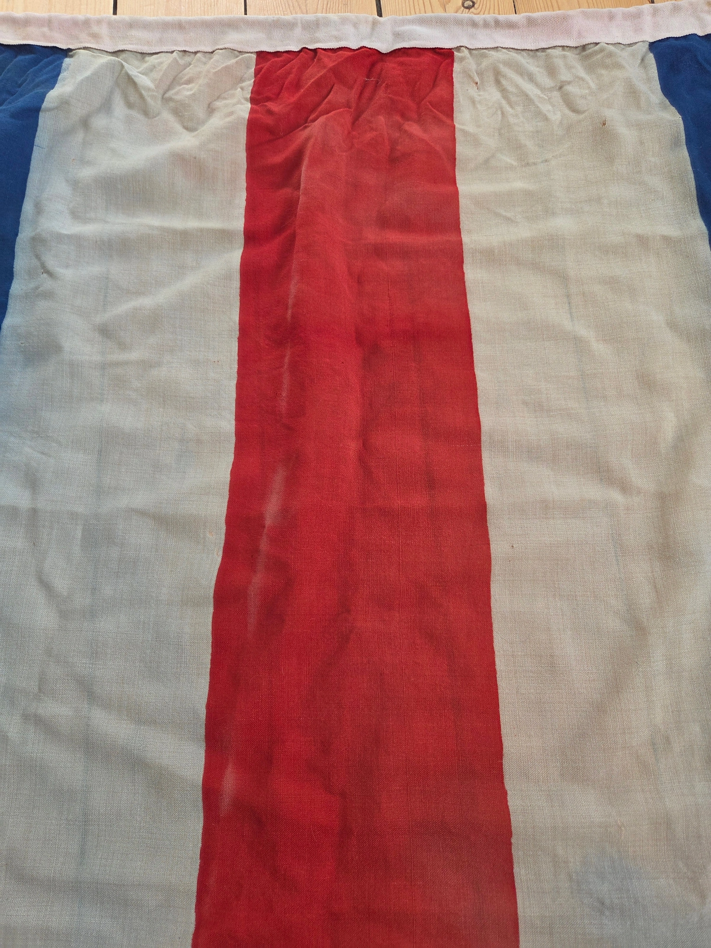
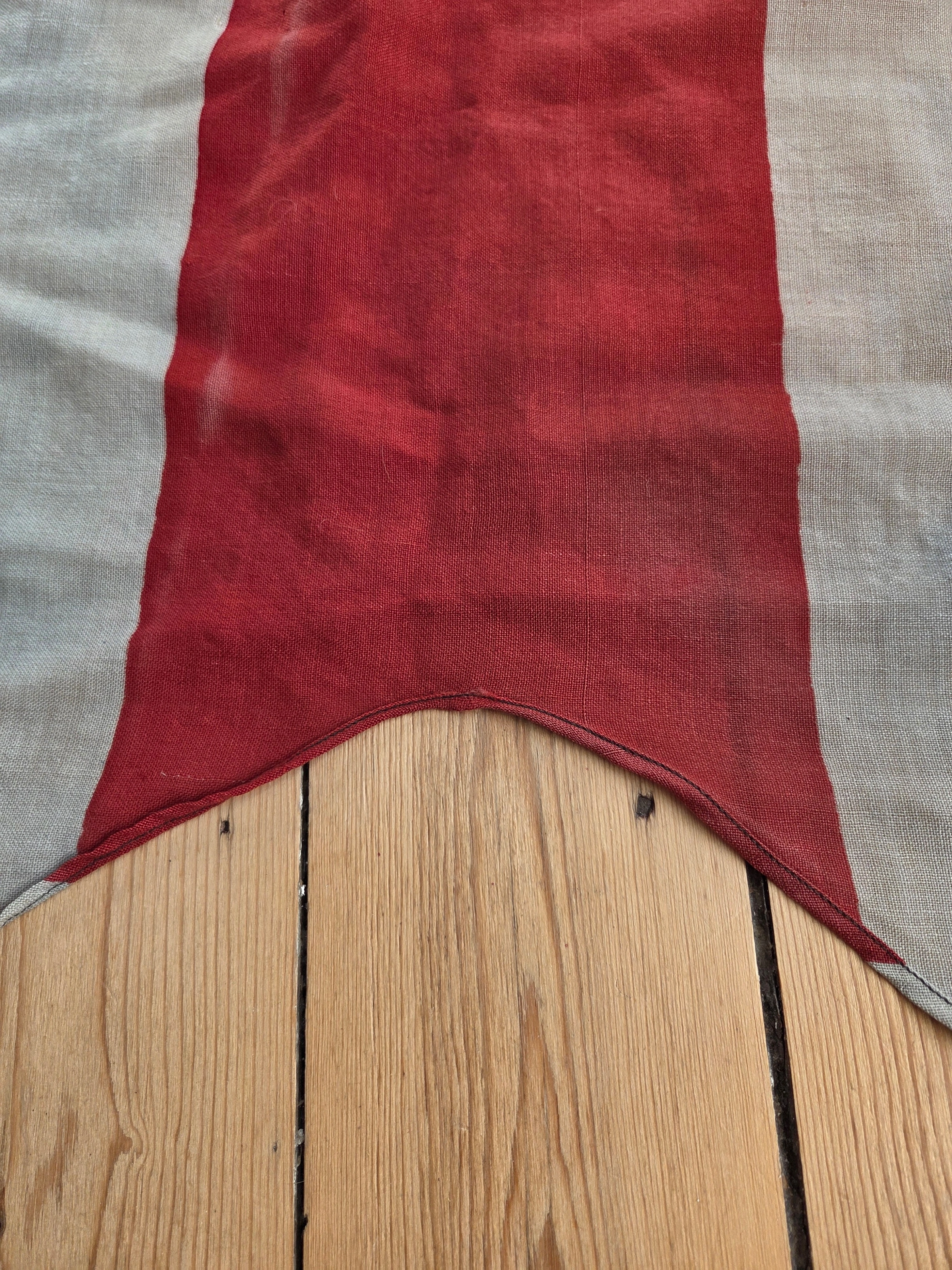
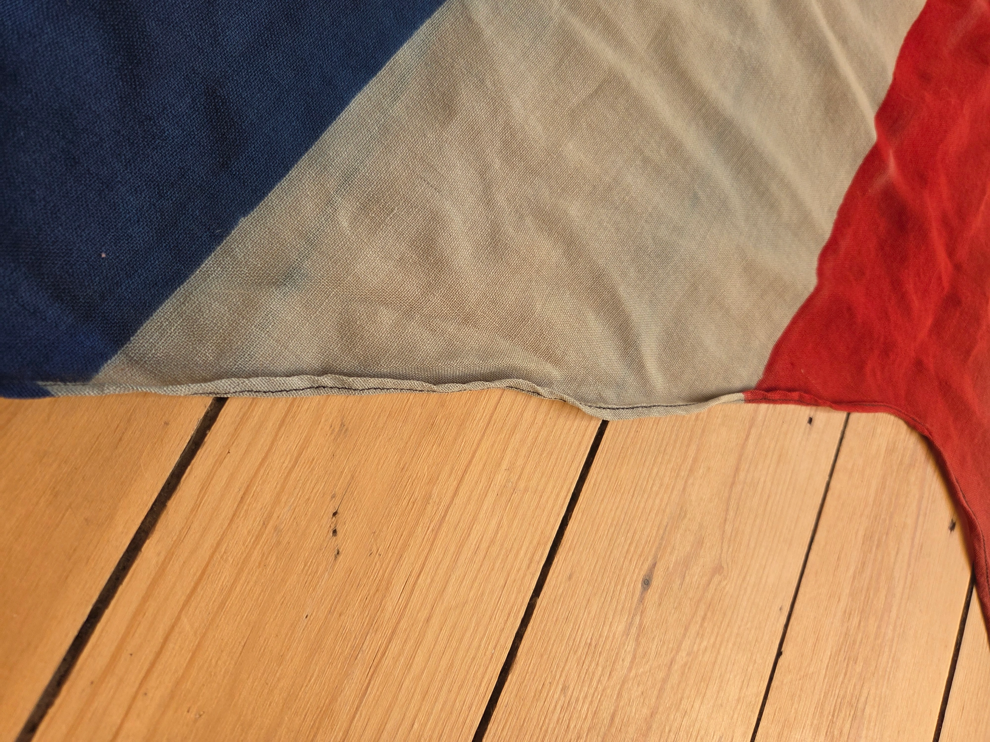
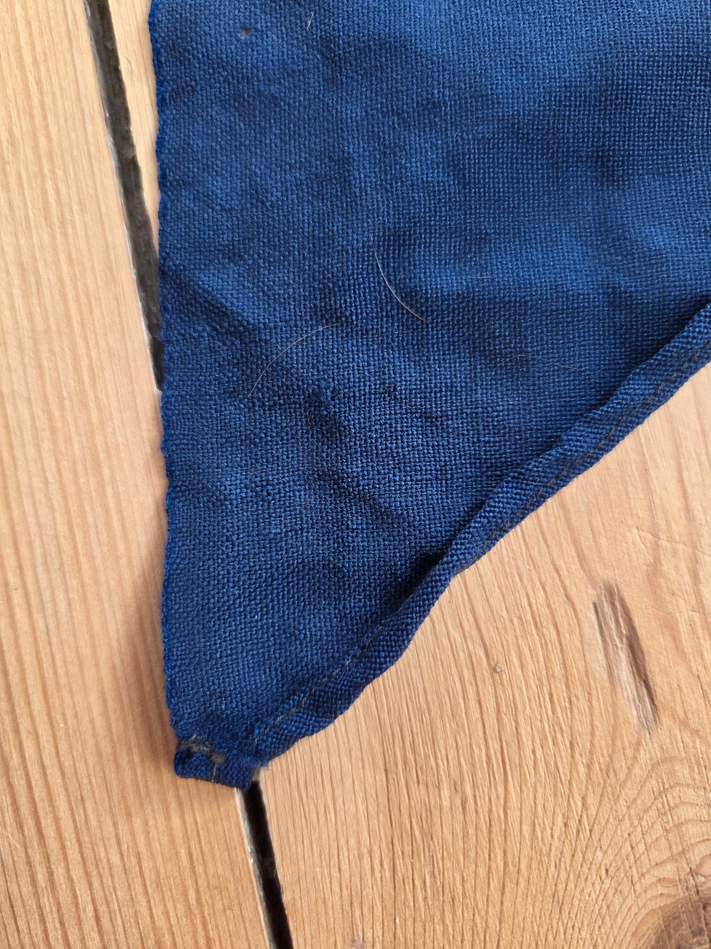
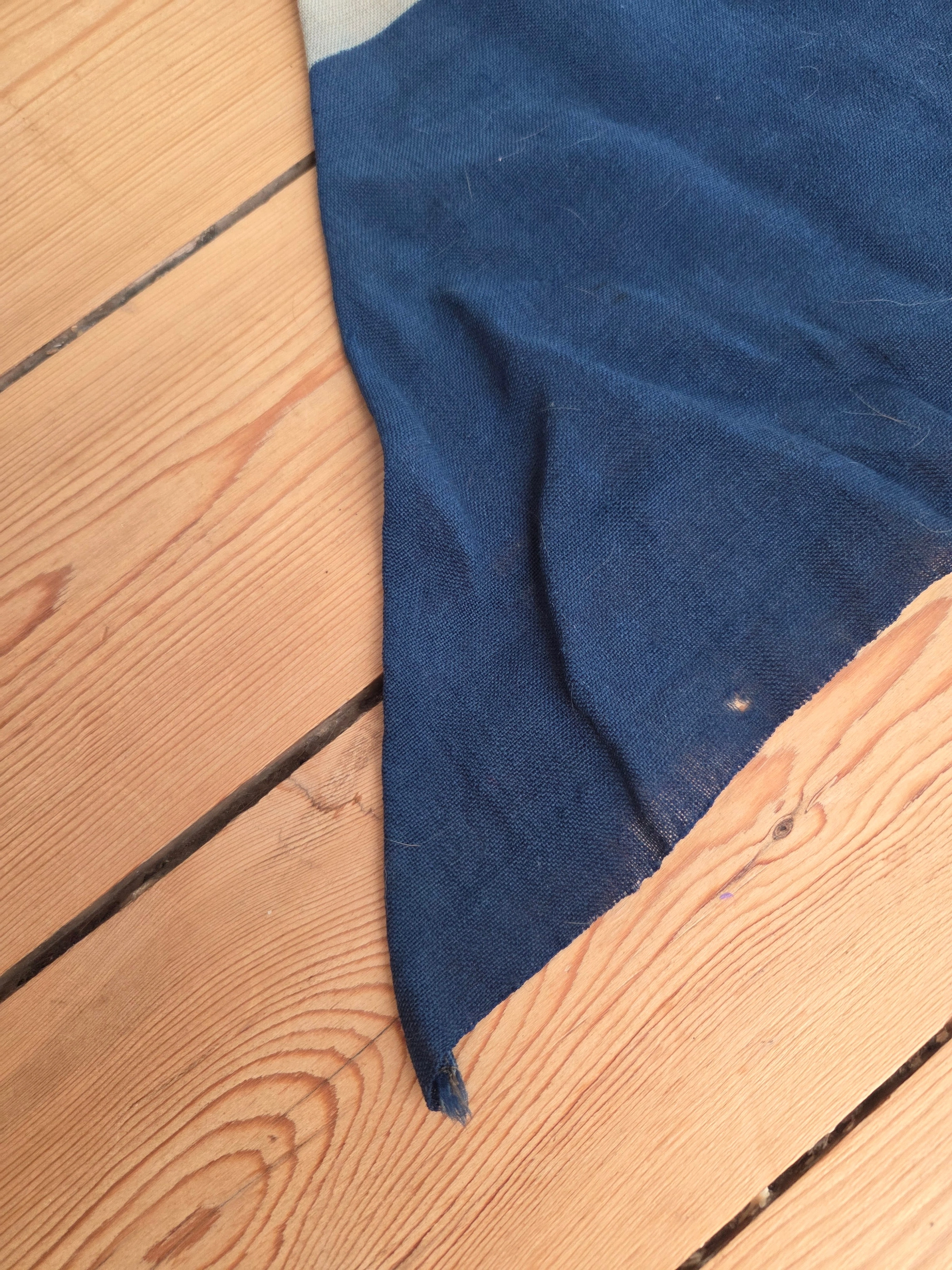
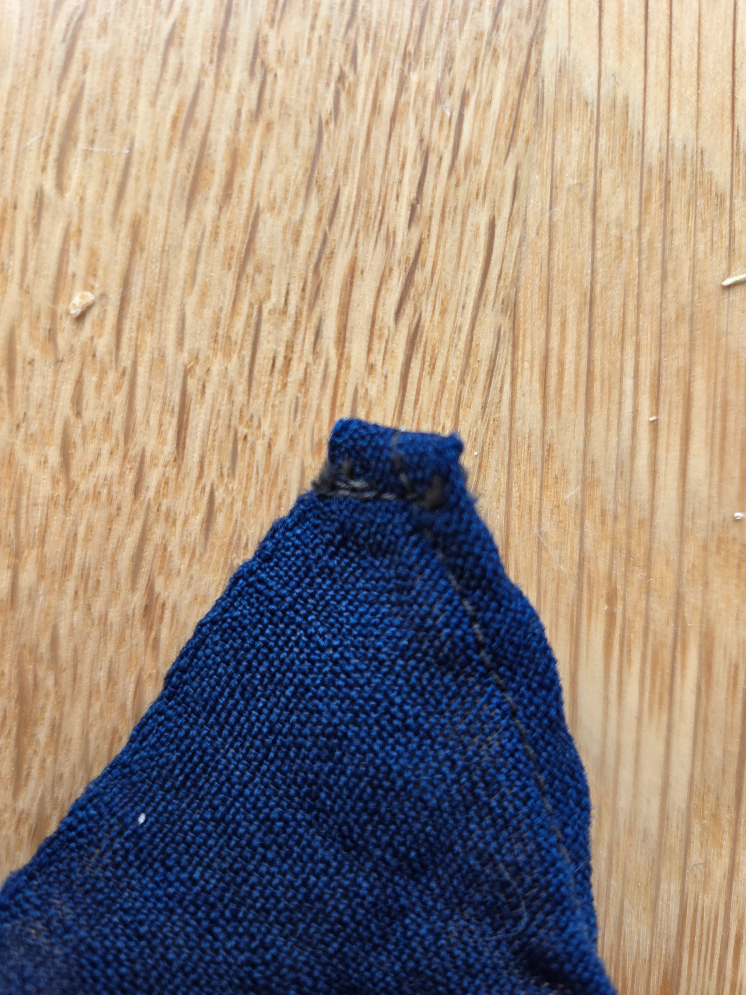
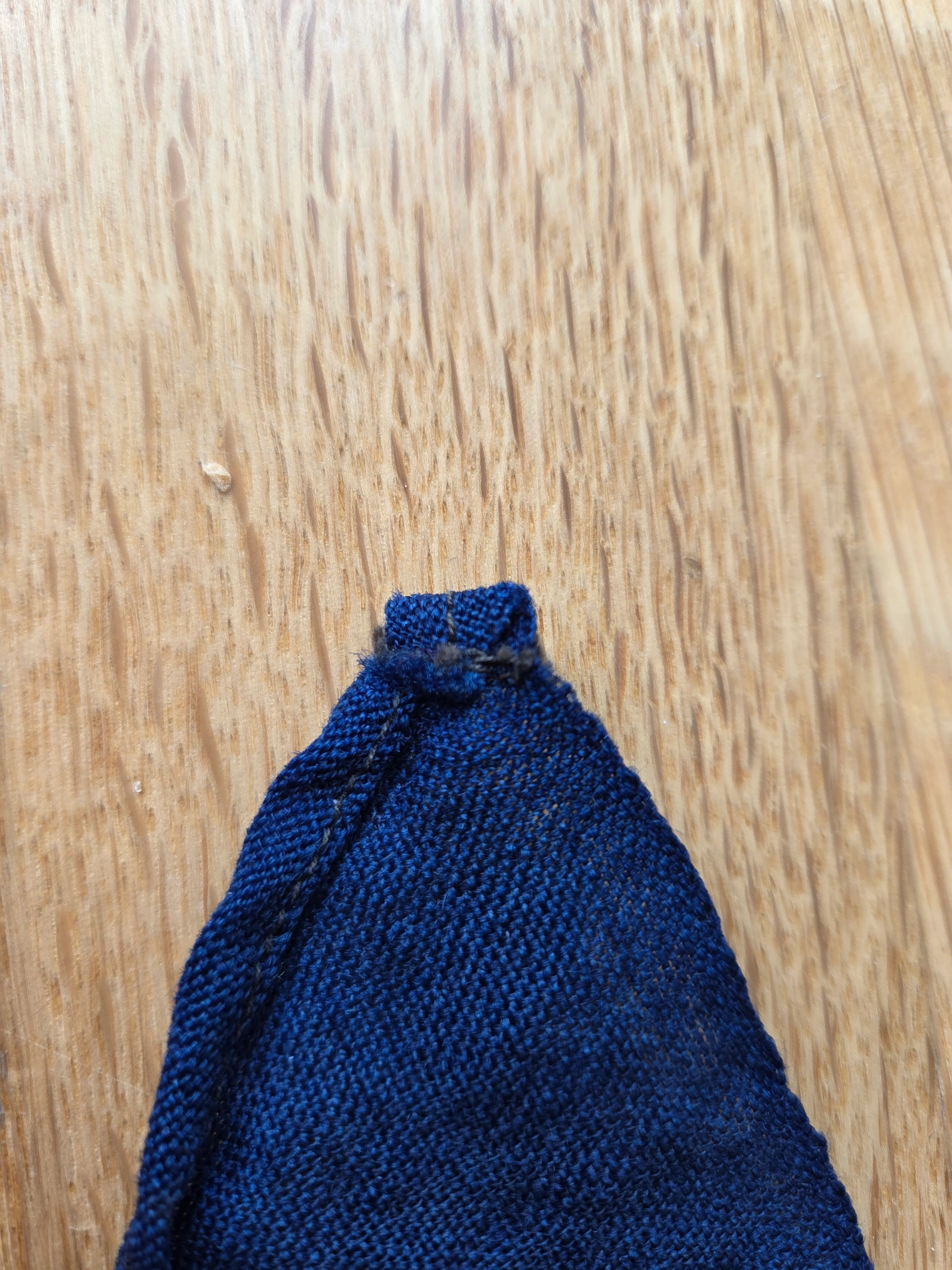
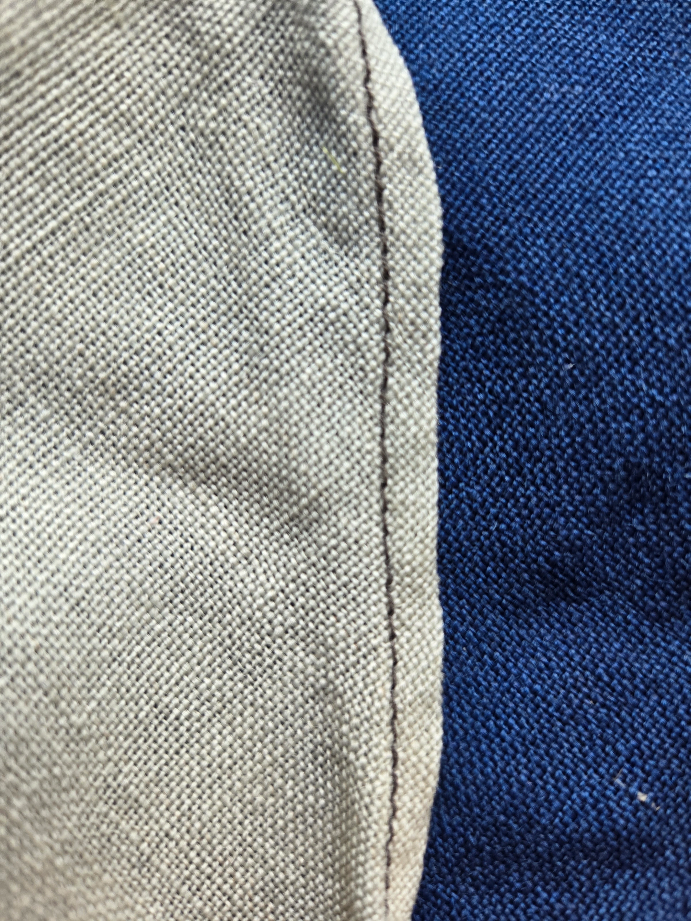
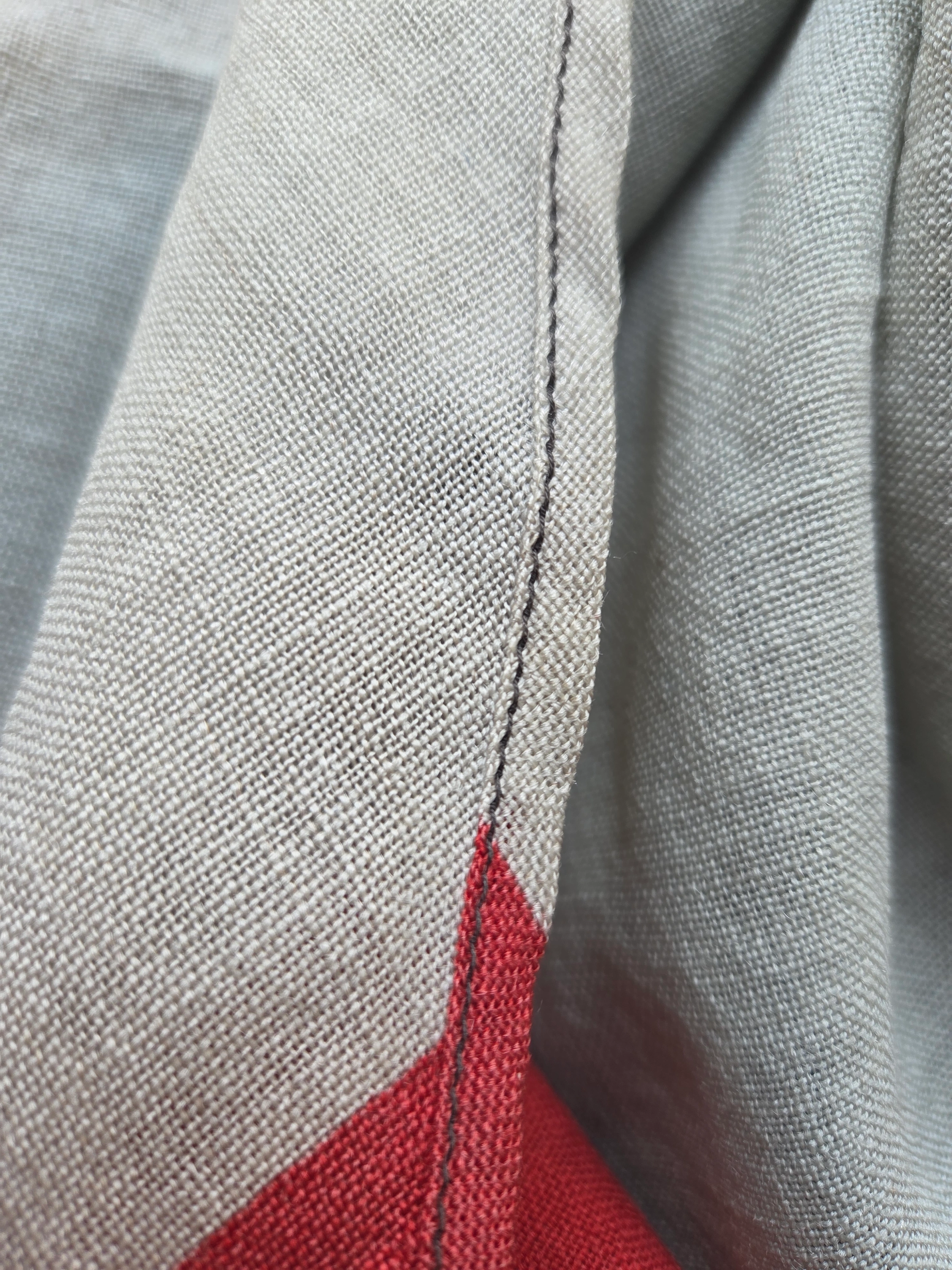
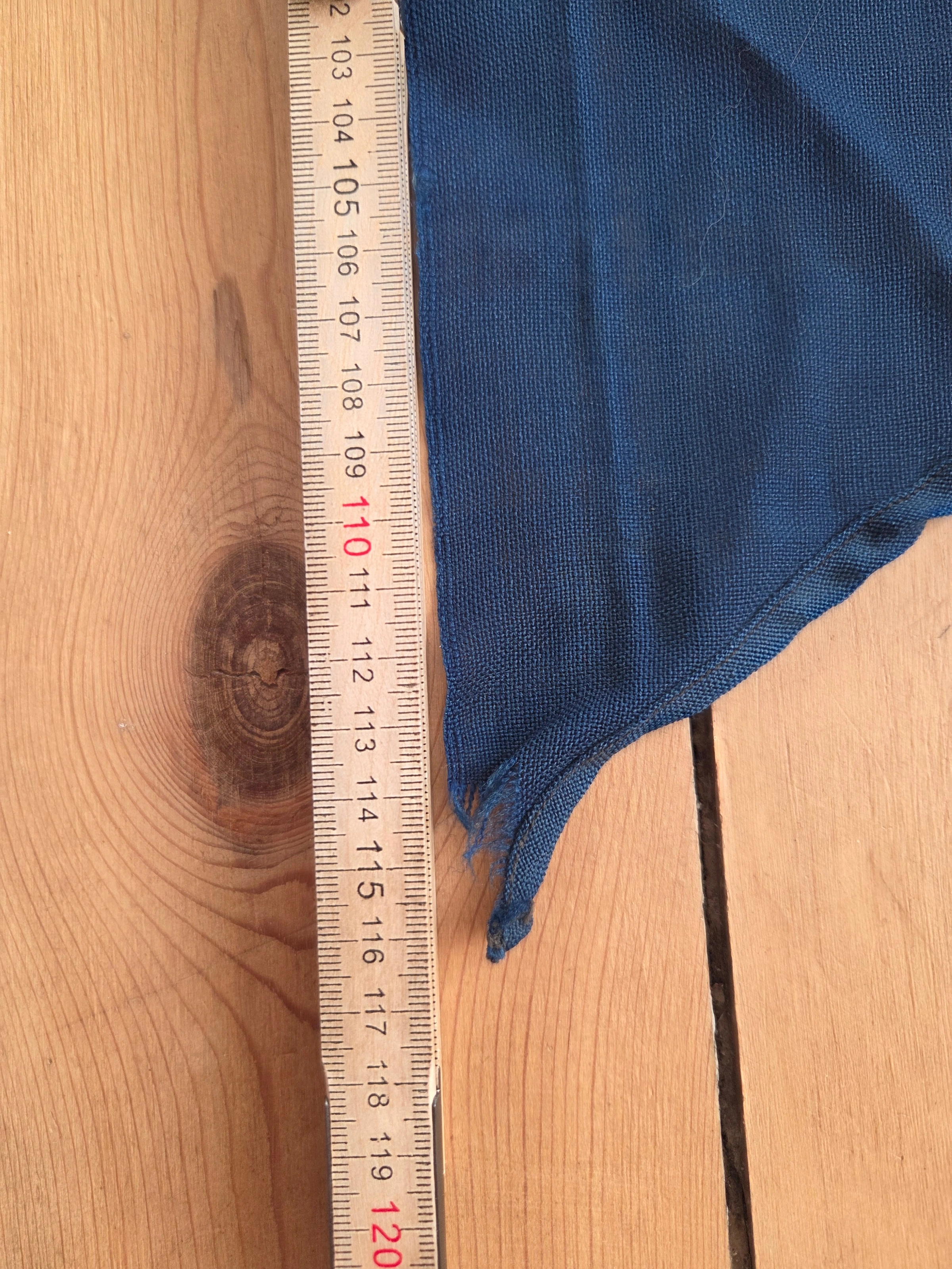
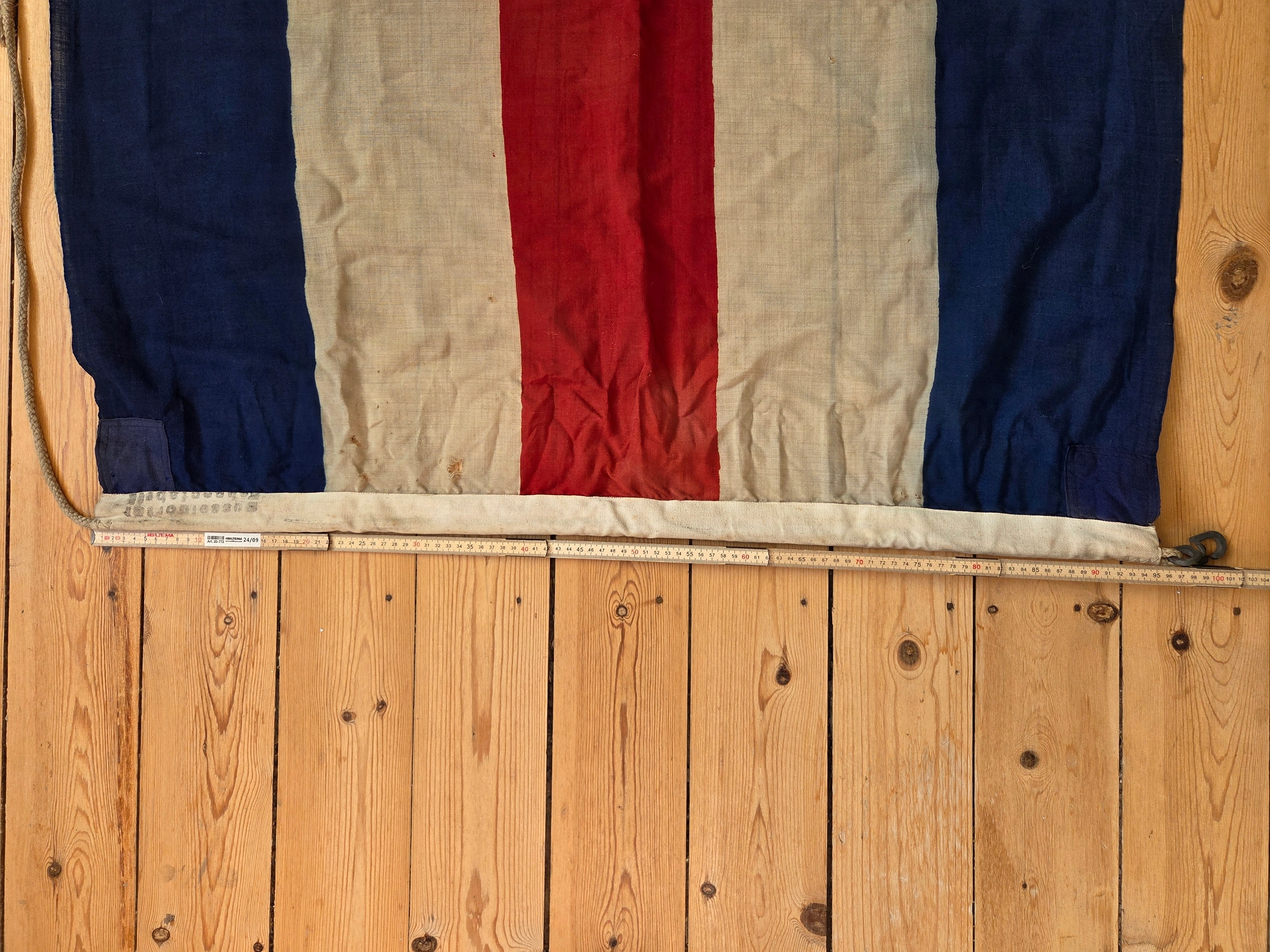
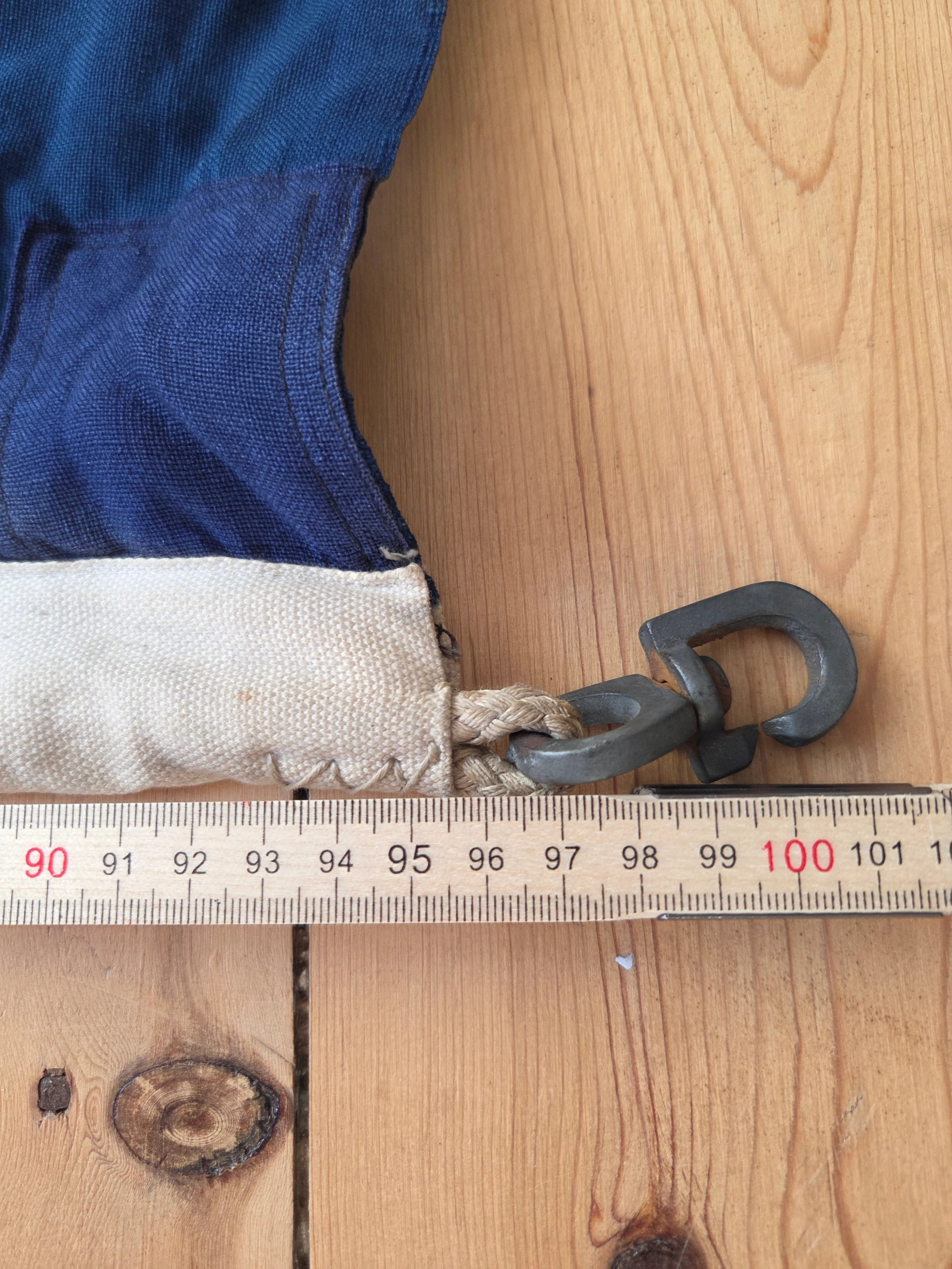
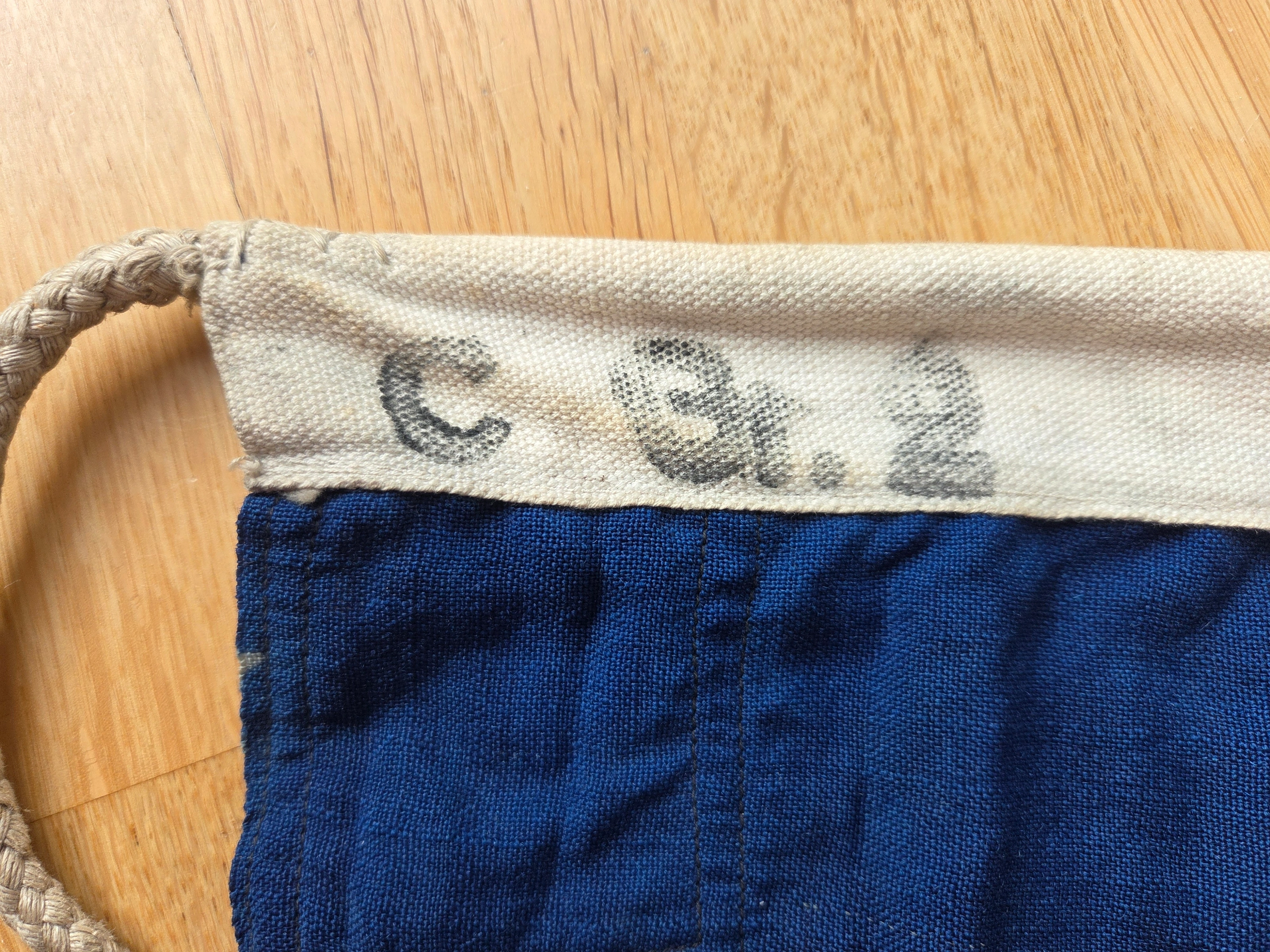
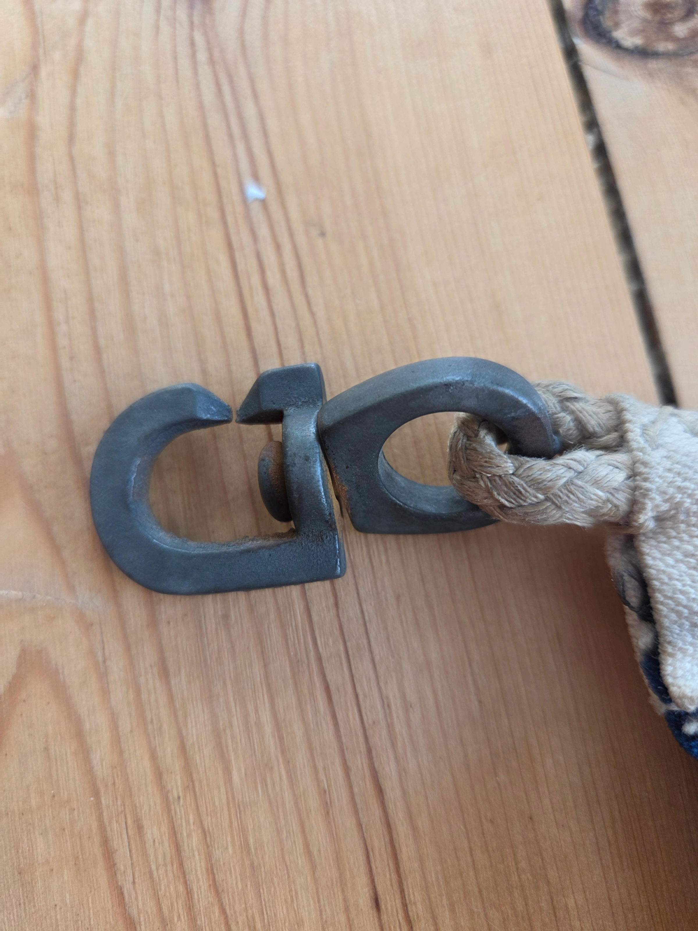
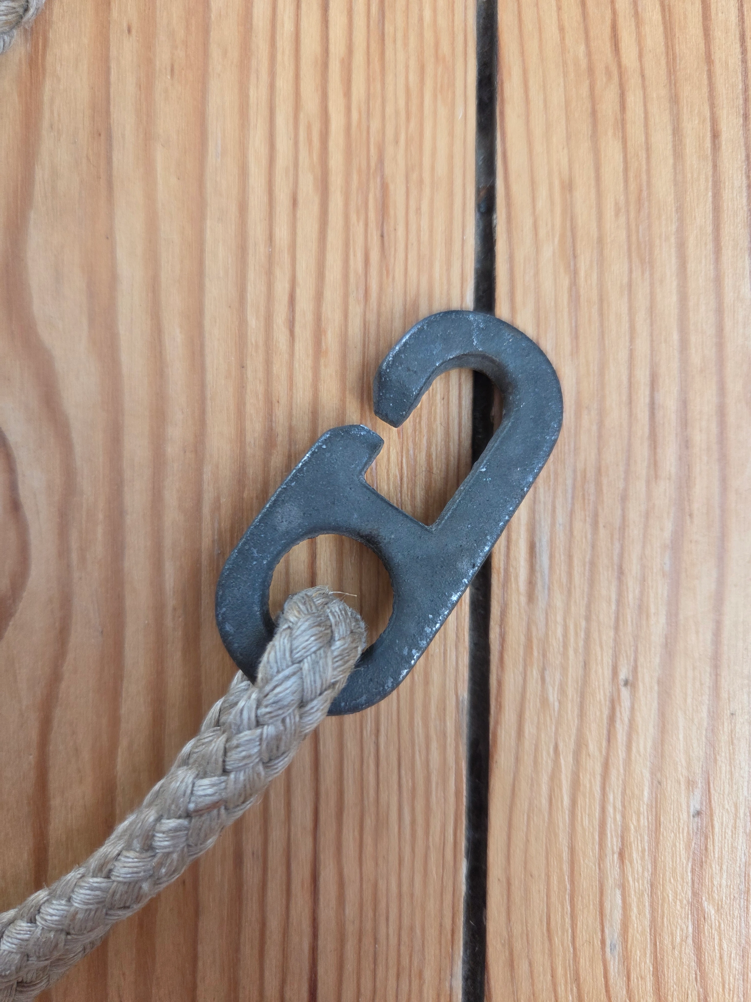
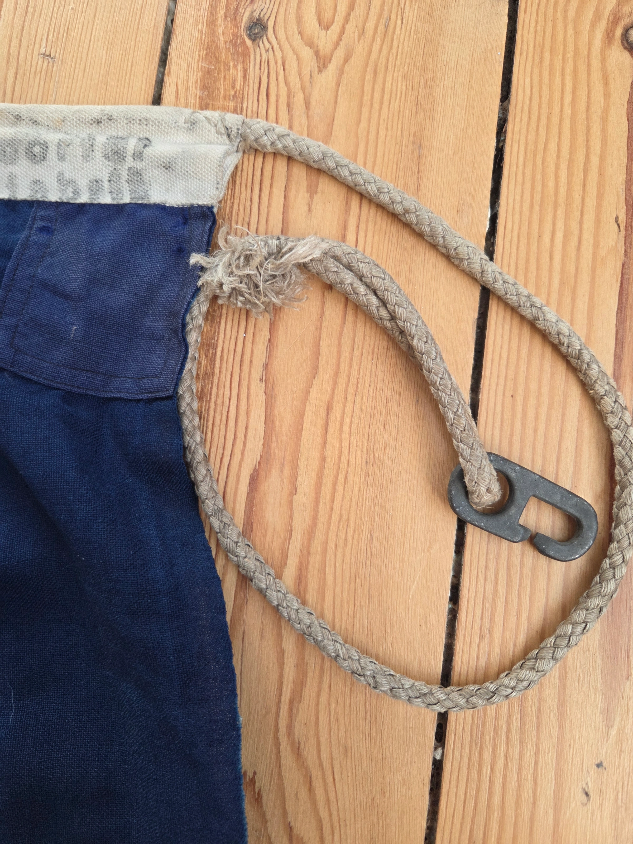
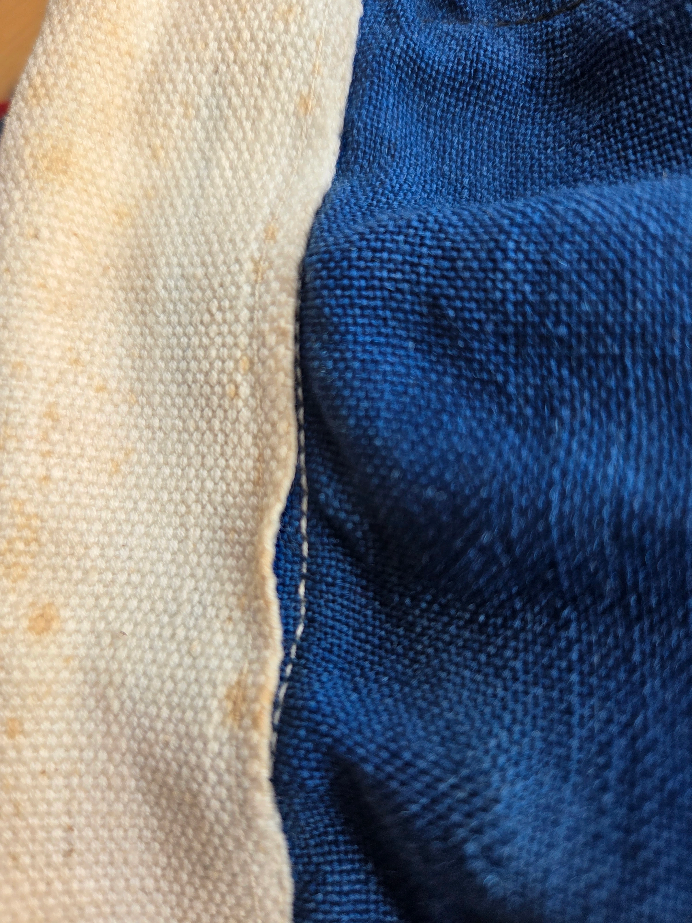
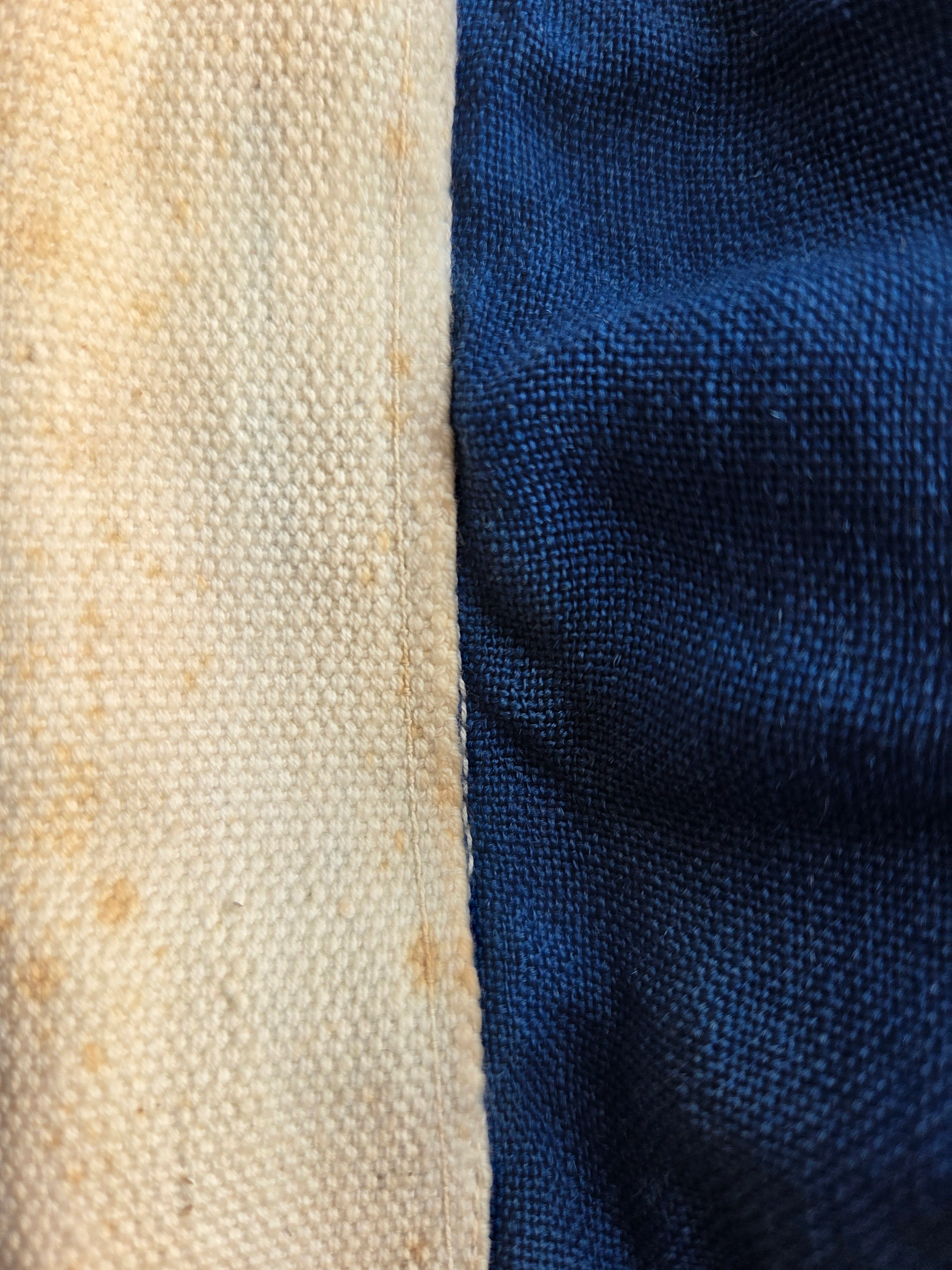
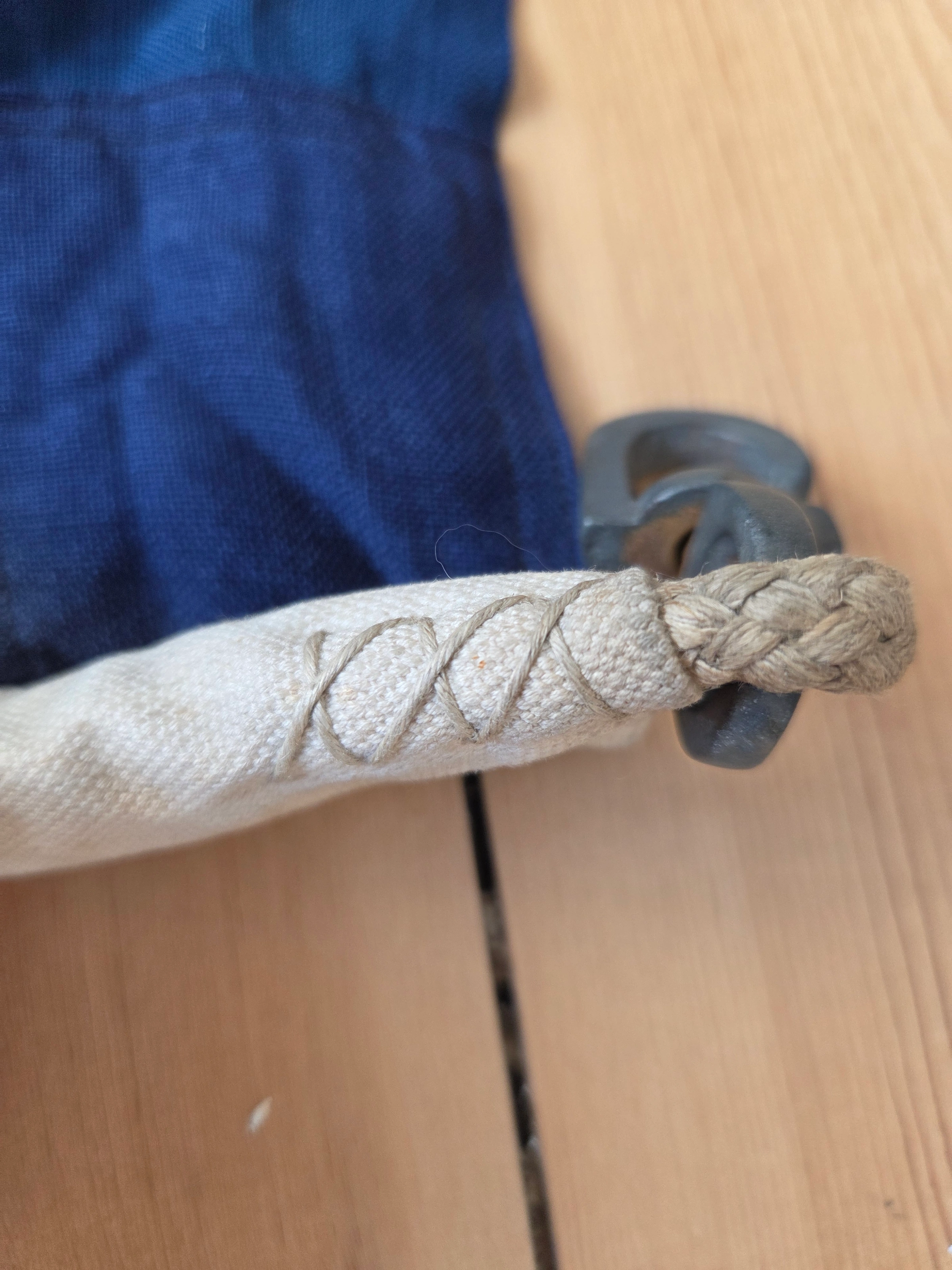
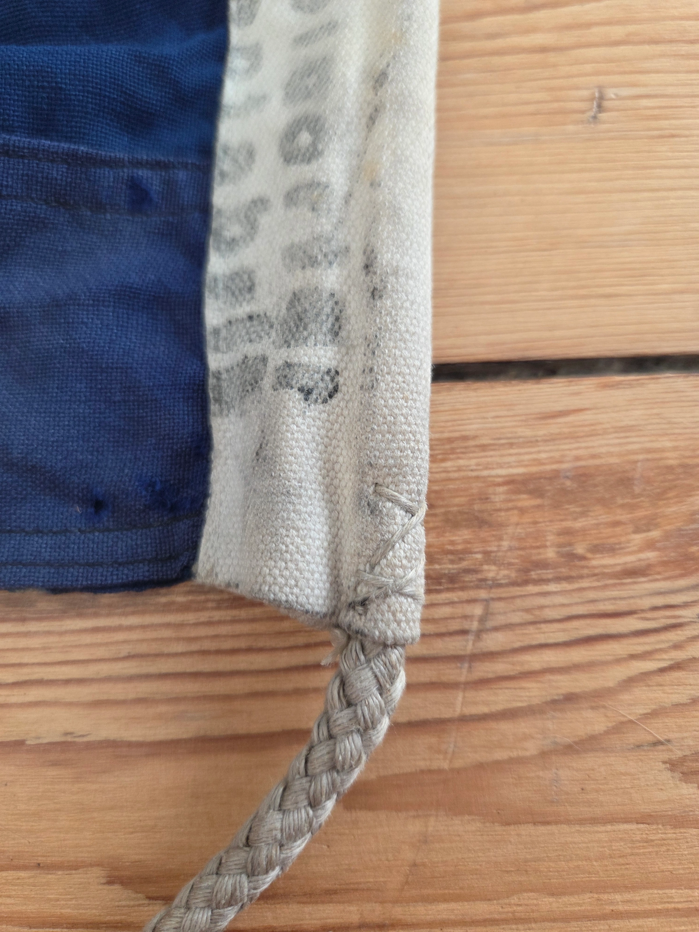
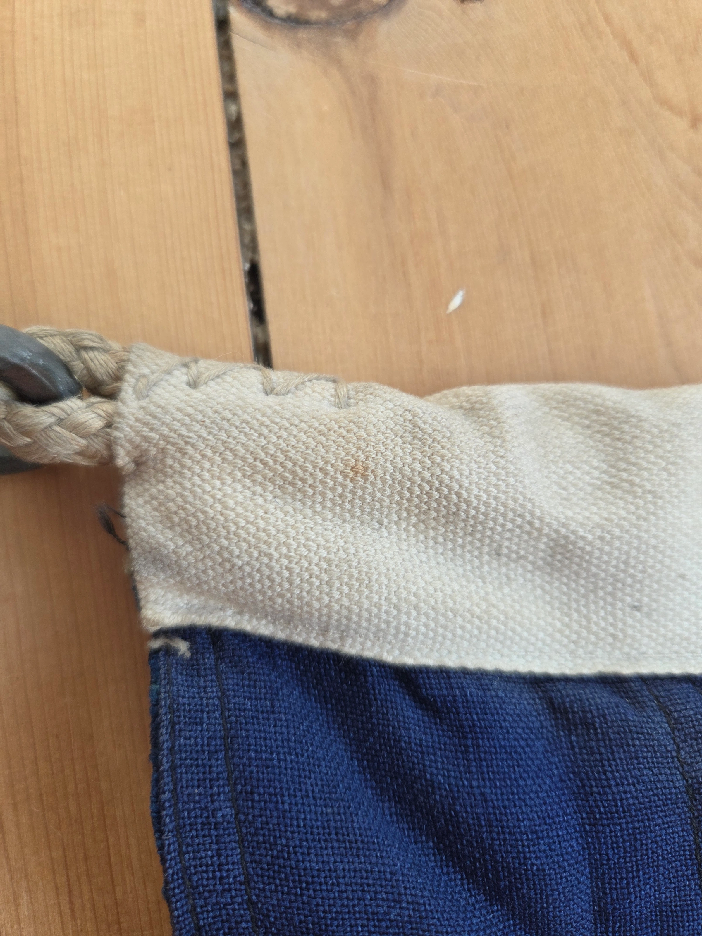
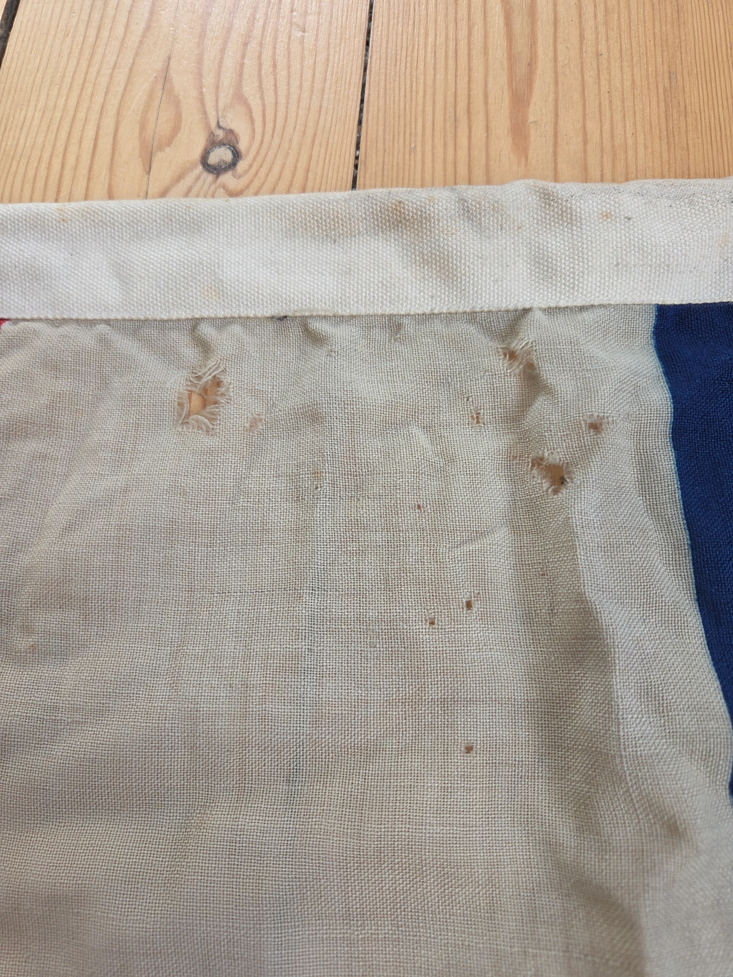
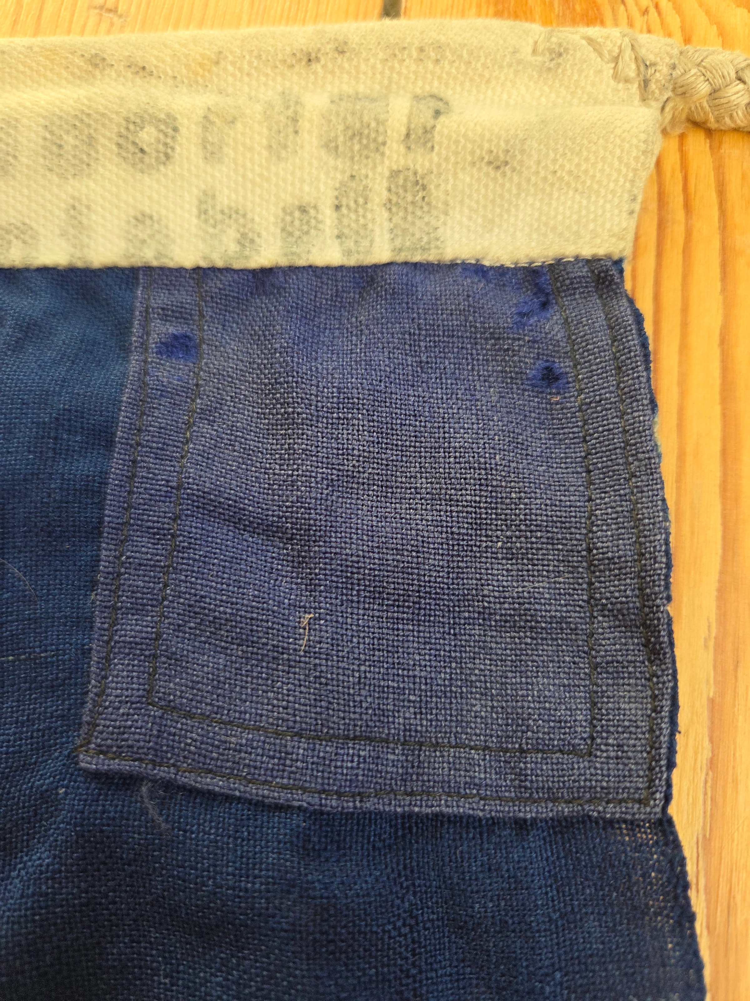
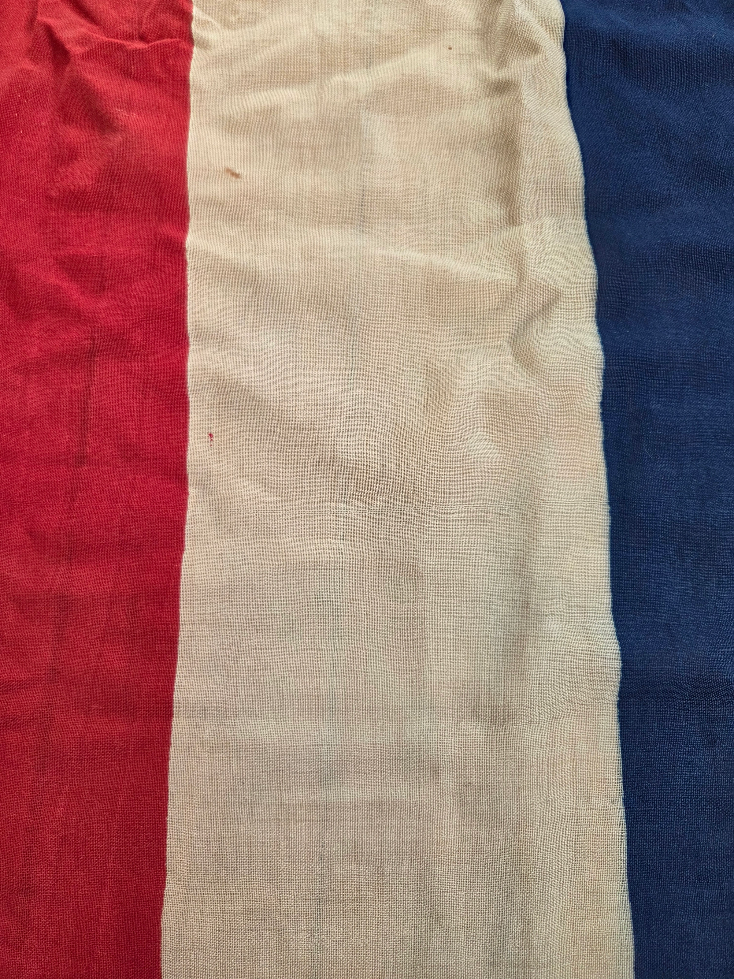
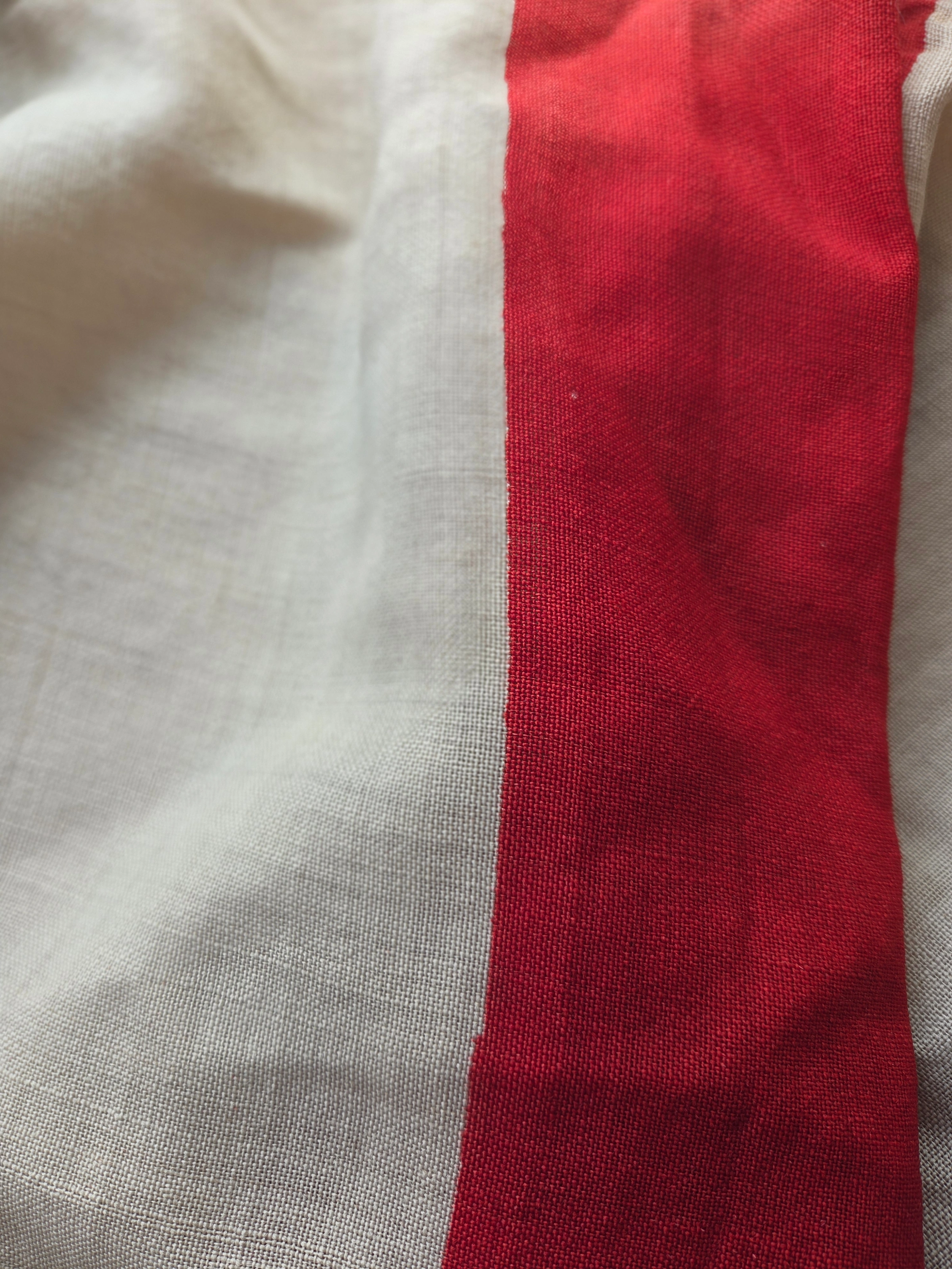
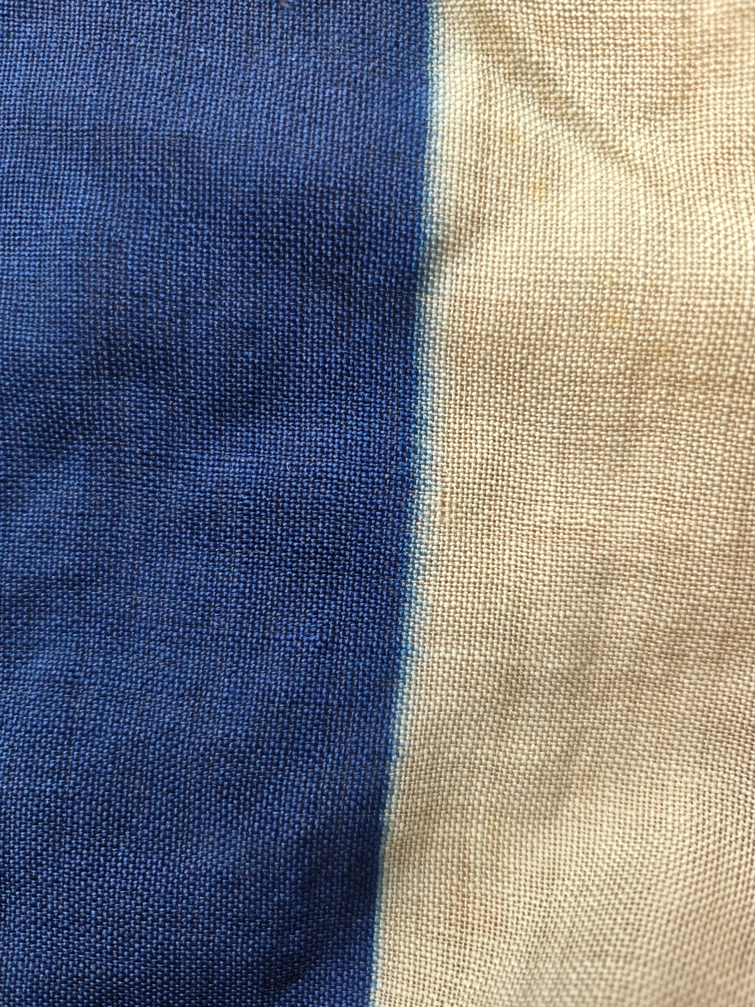
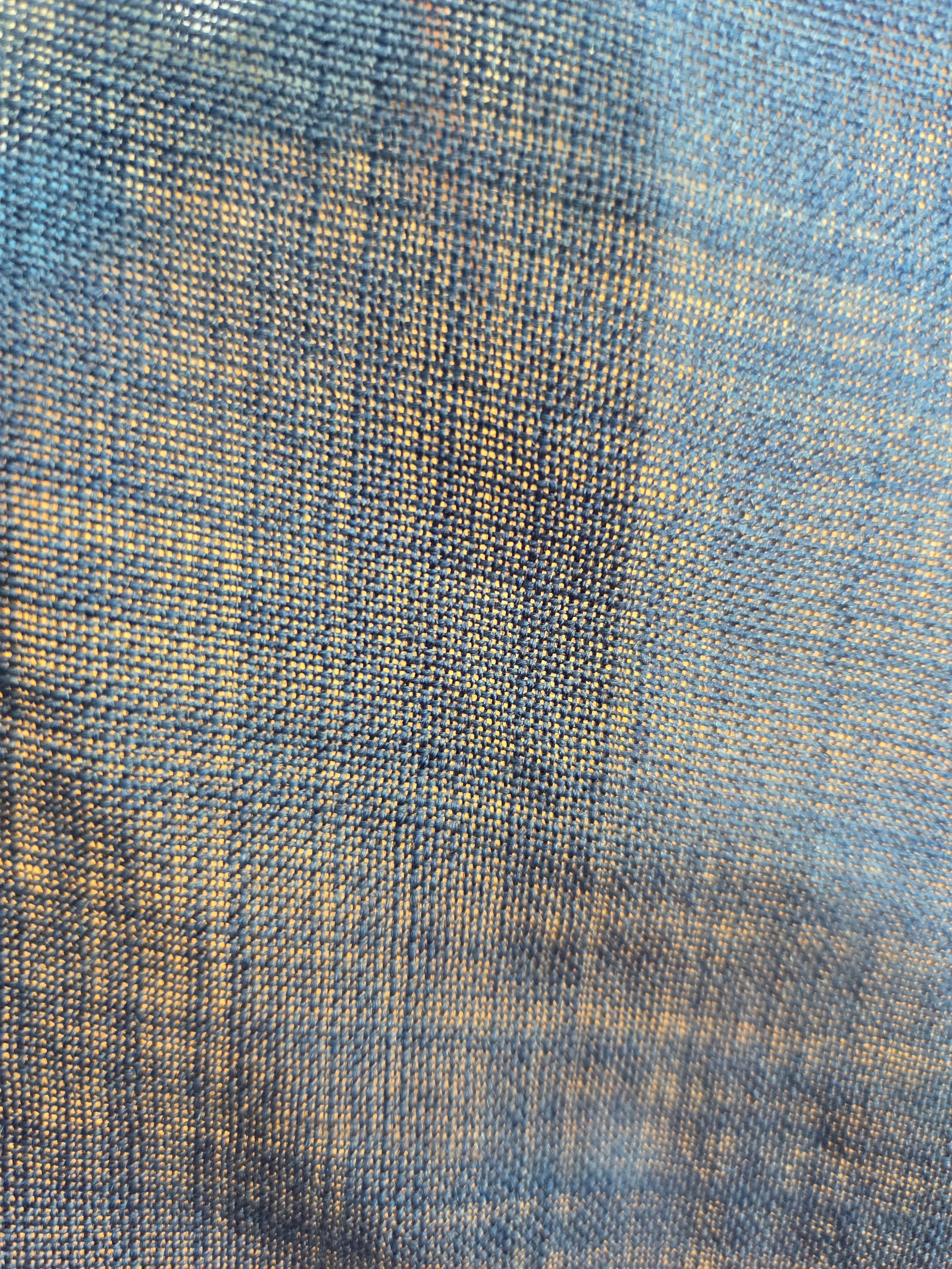
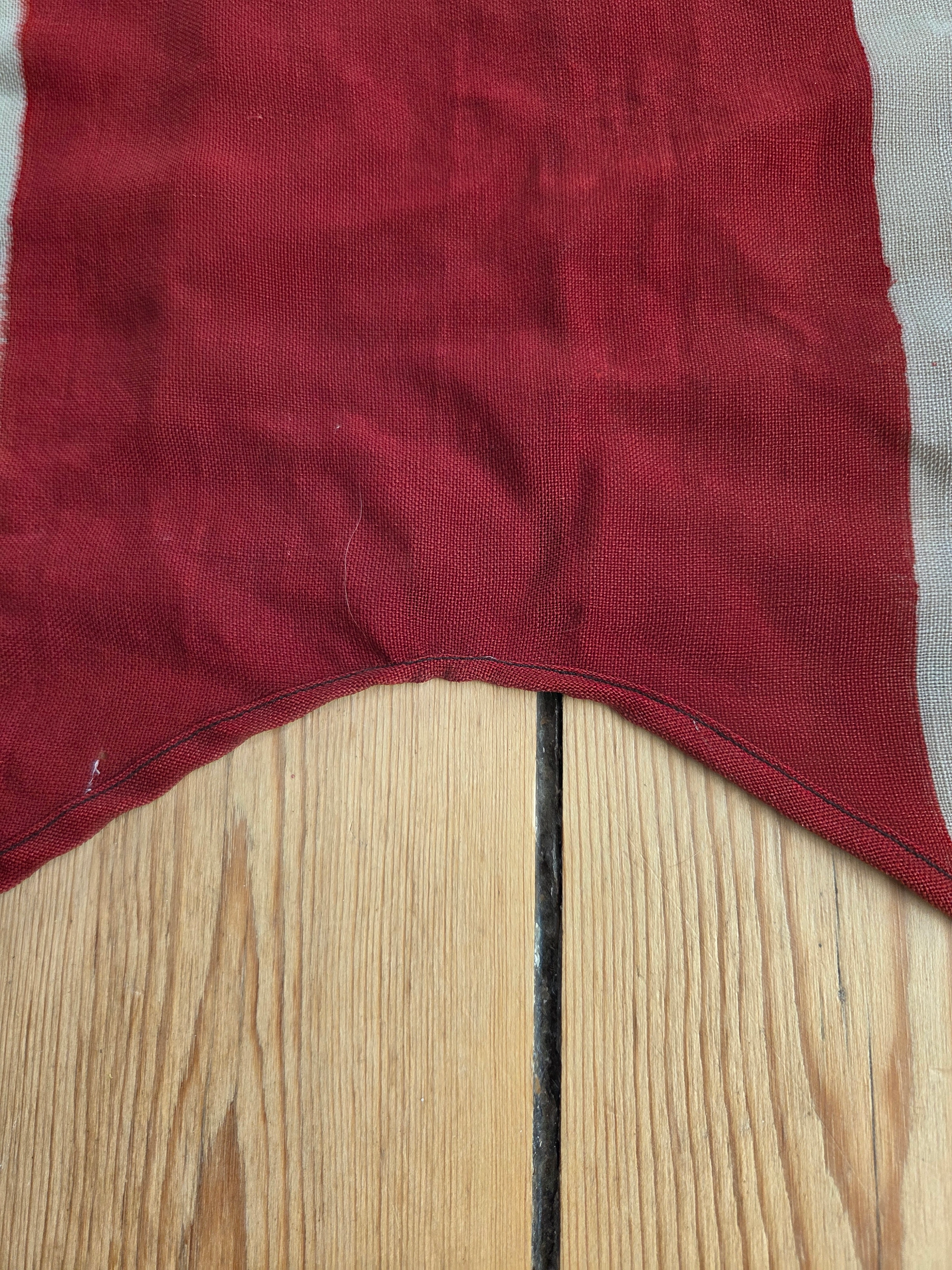
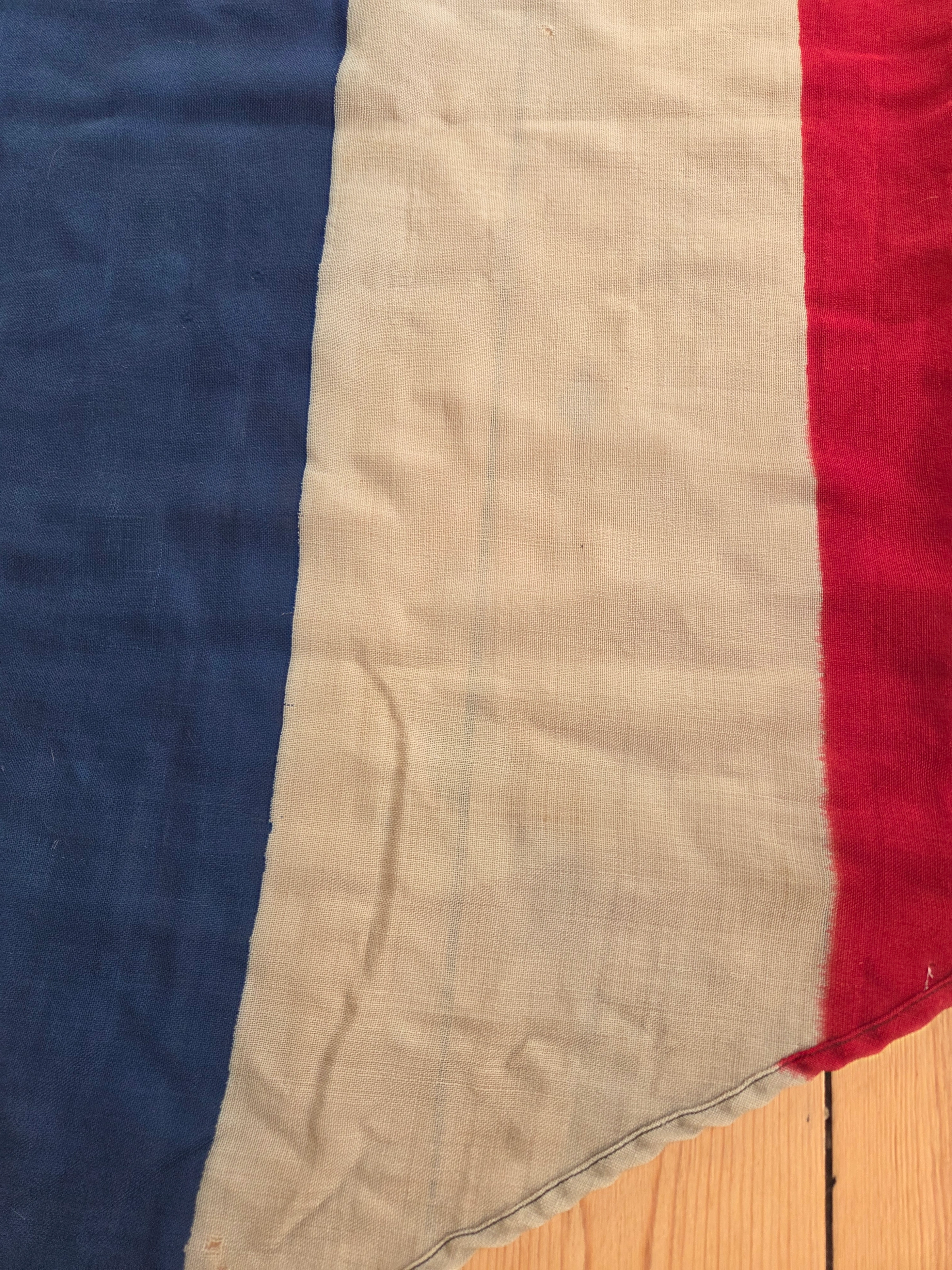
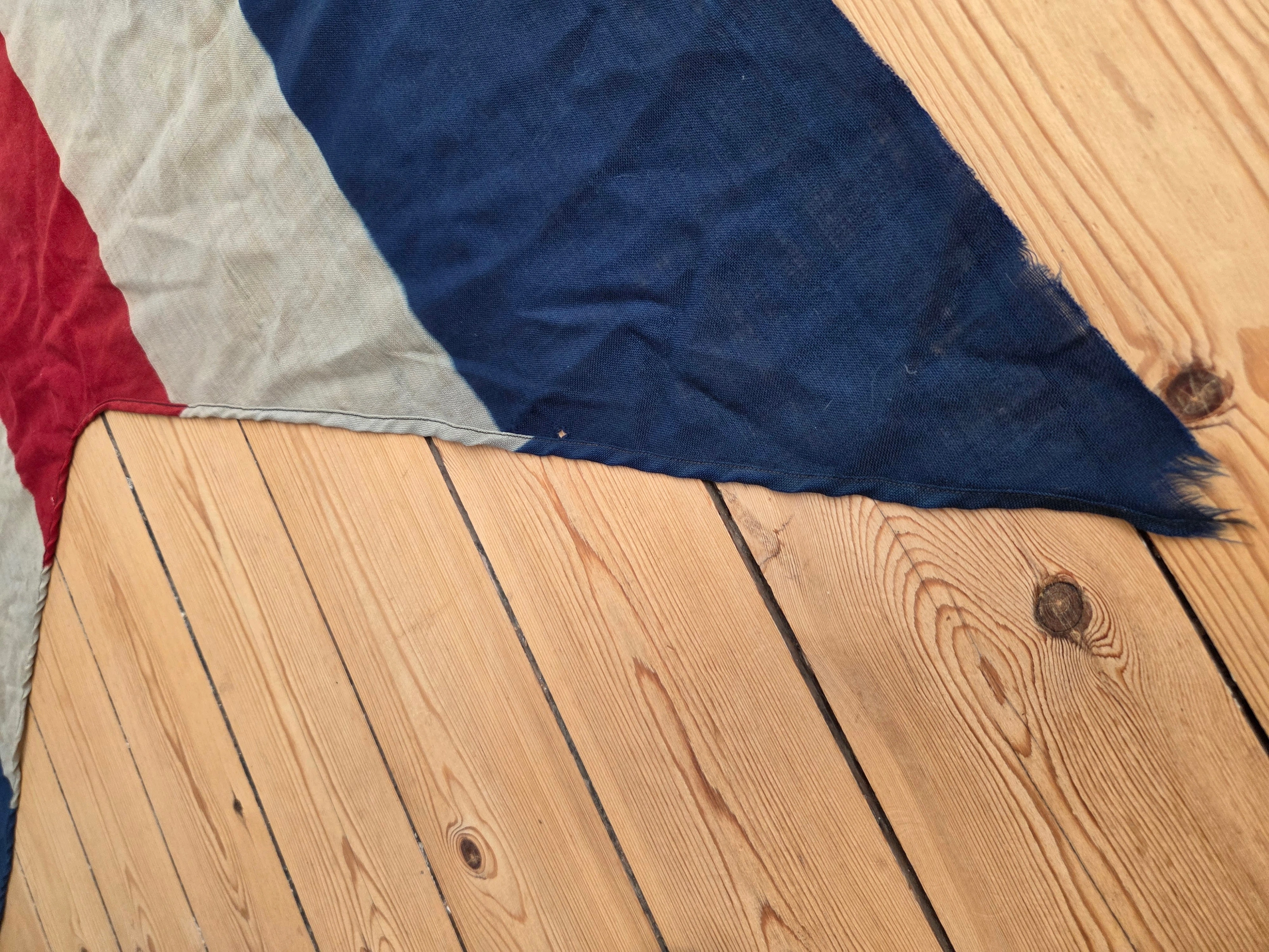
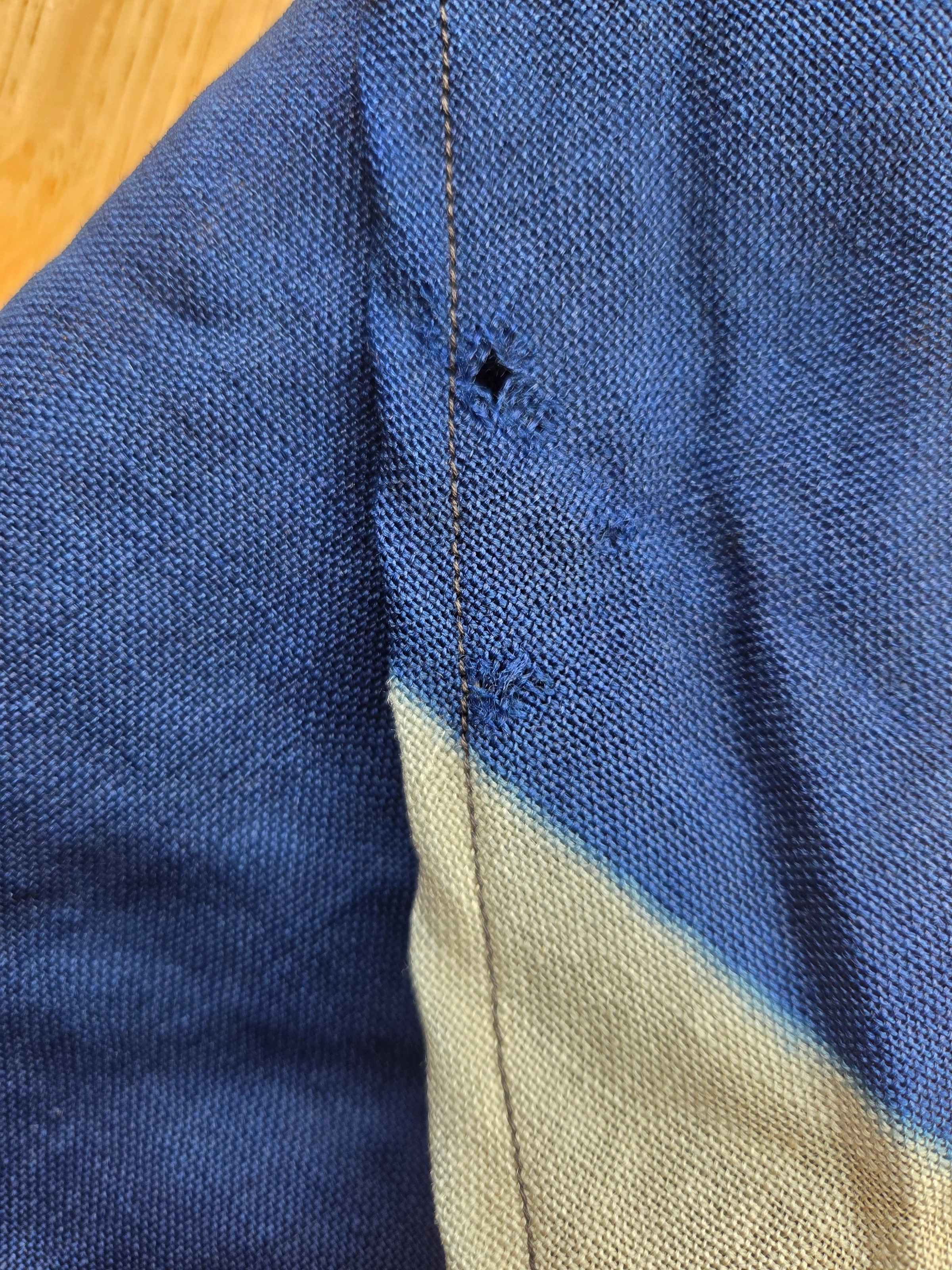
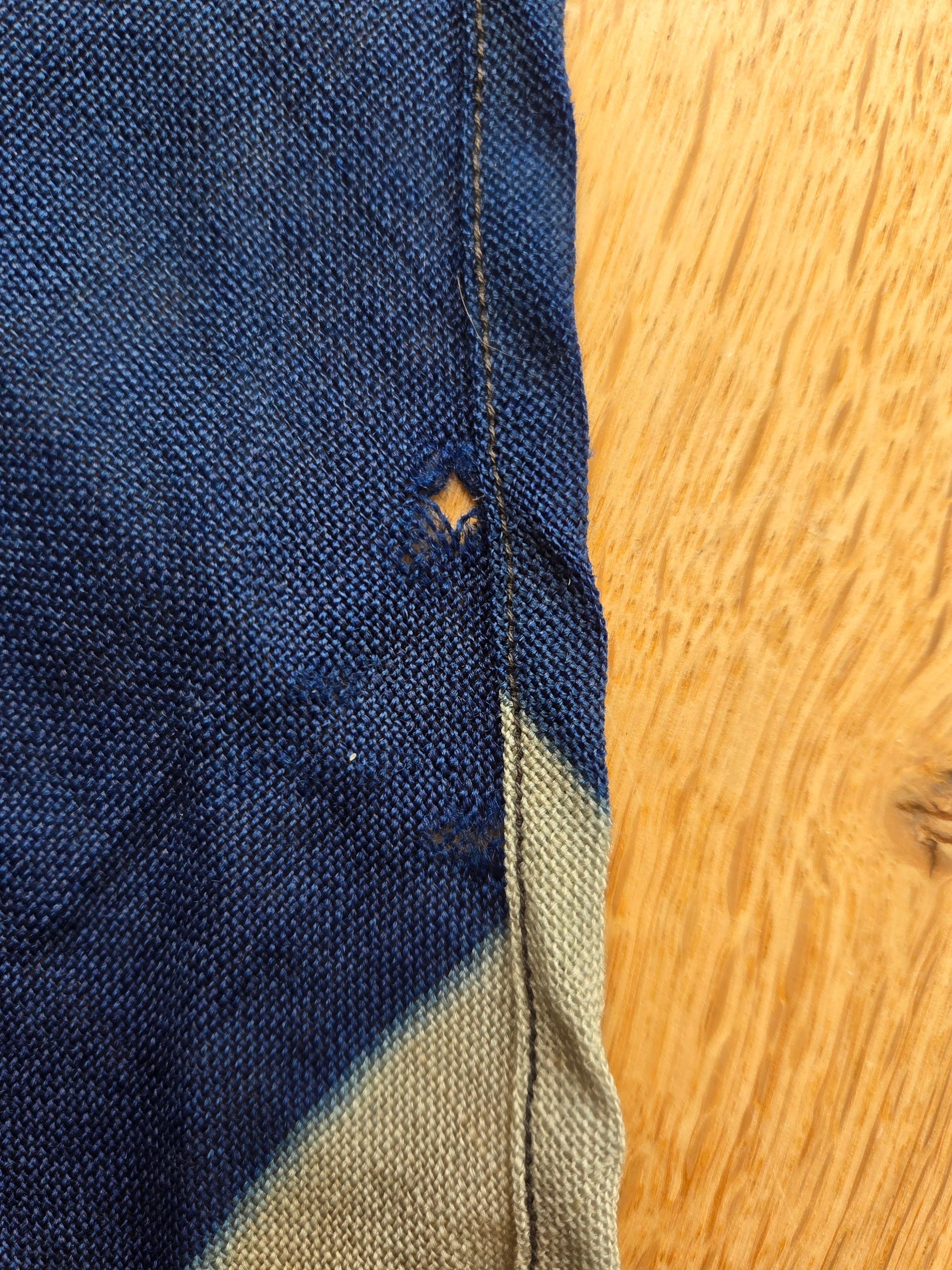
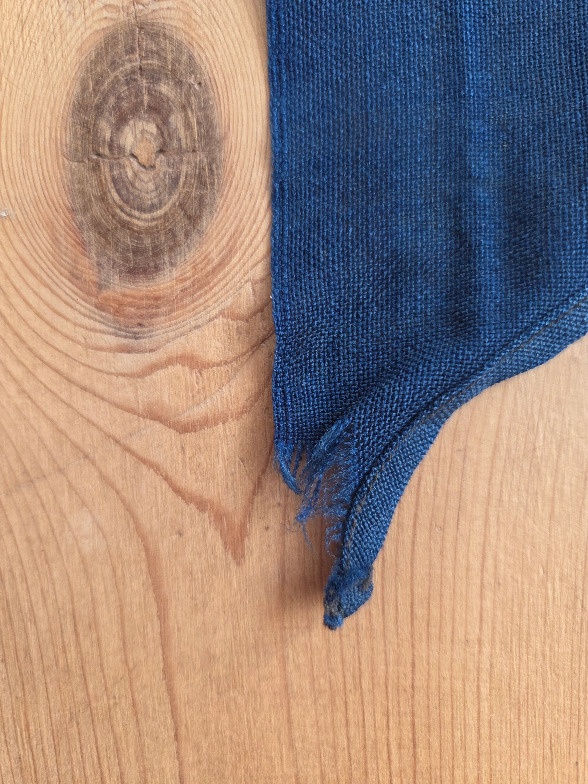
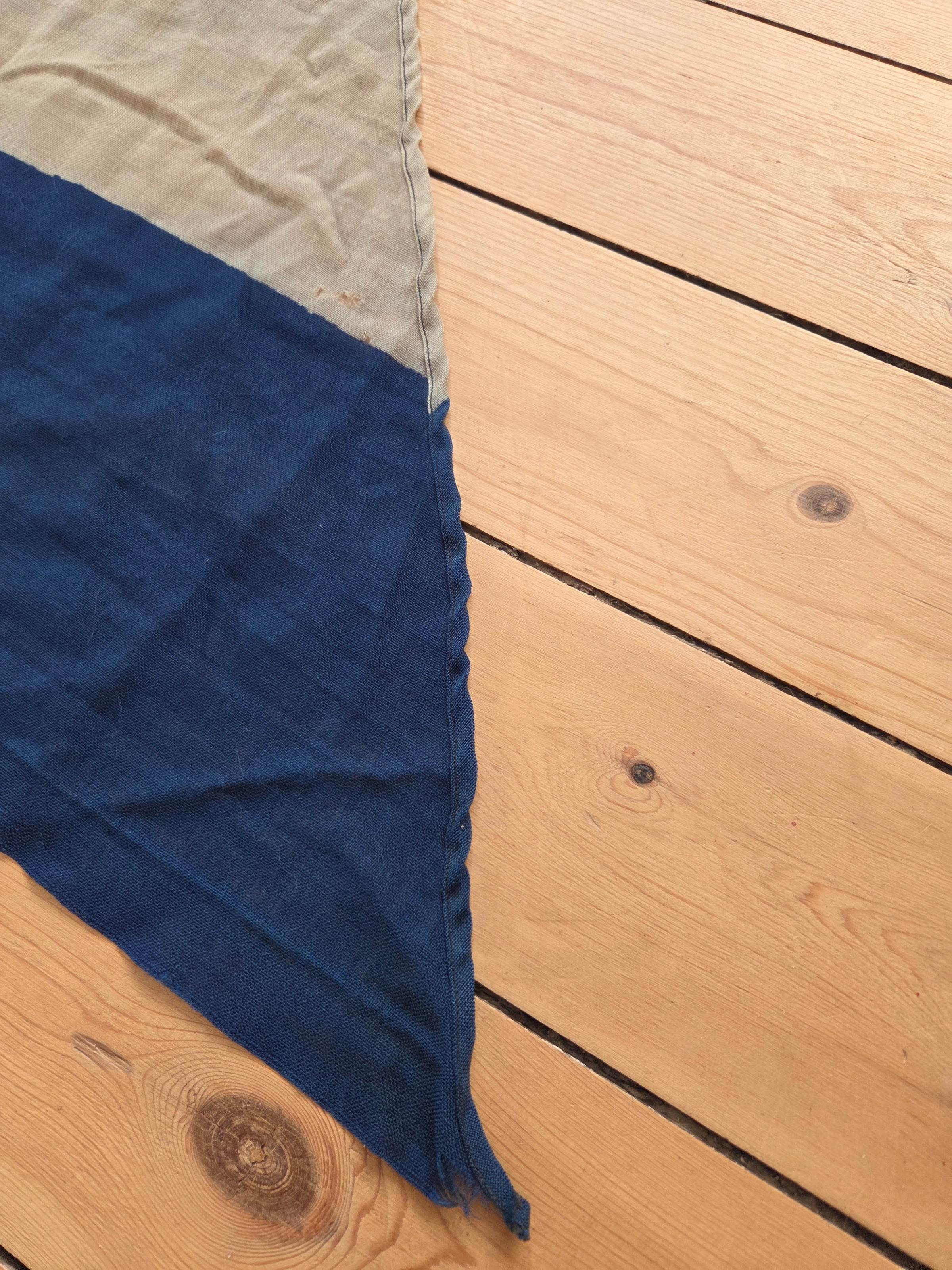
Both pieces are sewn in dense wool bunting with a coarse, period weave. The headers are heavy, stiff canvas for service use and fitted with solid Inglefield-style clips; seams are neat machine lockstitch using uniform black/dark thread throughout (no thread-colour change at the joins), consistent with late-1940s German workshop practice. The fly edges show physical fraying consistent with prolonged exposure to wind and salt air, not artificial wear. On each hoist the maker’s stamp “Düsseldorfer Fahnenfabrik” is clear, alongside “C” and “Gr. 2” markings.
Taken together, the “C” code and Gr. 2 size mark support the working assumption that these started life as standard signal flag C blanks and were converted into C-Doppelstander by cutting a swallowtail — exactly as described in the Allied radio order (“…with a triangle cut from the fly thus transforming it into a burgee”) and later codified in Annex A to Law No. 39. This conversion is entirely plausible for a resource-tight post-war workshop (reuse over fresh yardage). The cut itself presents as a practical workshop template (see Section 7), not a mathematically exact 90° schematic. This correlation between the photographs and both surviving examples indicates that makers worked to a consistent, functional pattern rather than the theoretical right angle prescribed in the regulation.
Measurements and observations are naturally approximate; any inferred geometry or ratio comparisons (Sections 6 and 7) should therefore be read with due caution. The present section records direct, physical characteristics only.
A macro of the frayed swallowtail shows the black stitching thread; the fibre sample in Section 8a was taken from this point.

Published summaries disagree on the base ratio of the C-Doppelstander: some give 2:3 (Imperial/Weimar precedent), others 3:5 (Nazi-period practice).
Before the measurements, a quick key to the markings on our flags: Gr. (Größe) is the German signal-flag size class — the stock workshops and ships actually had on the shelves:
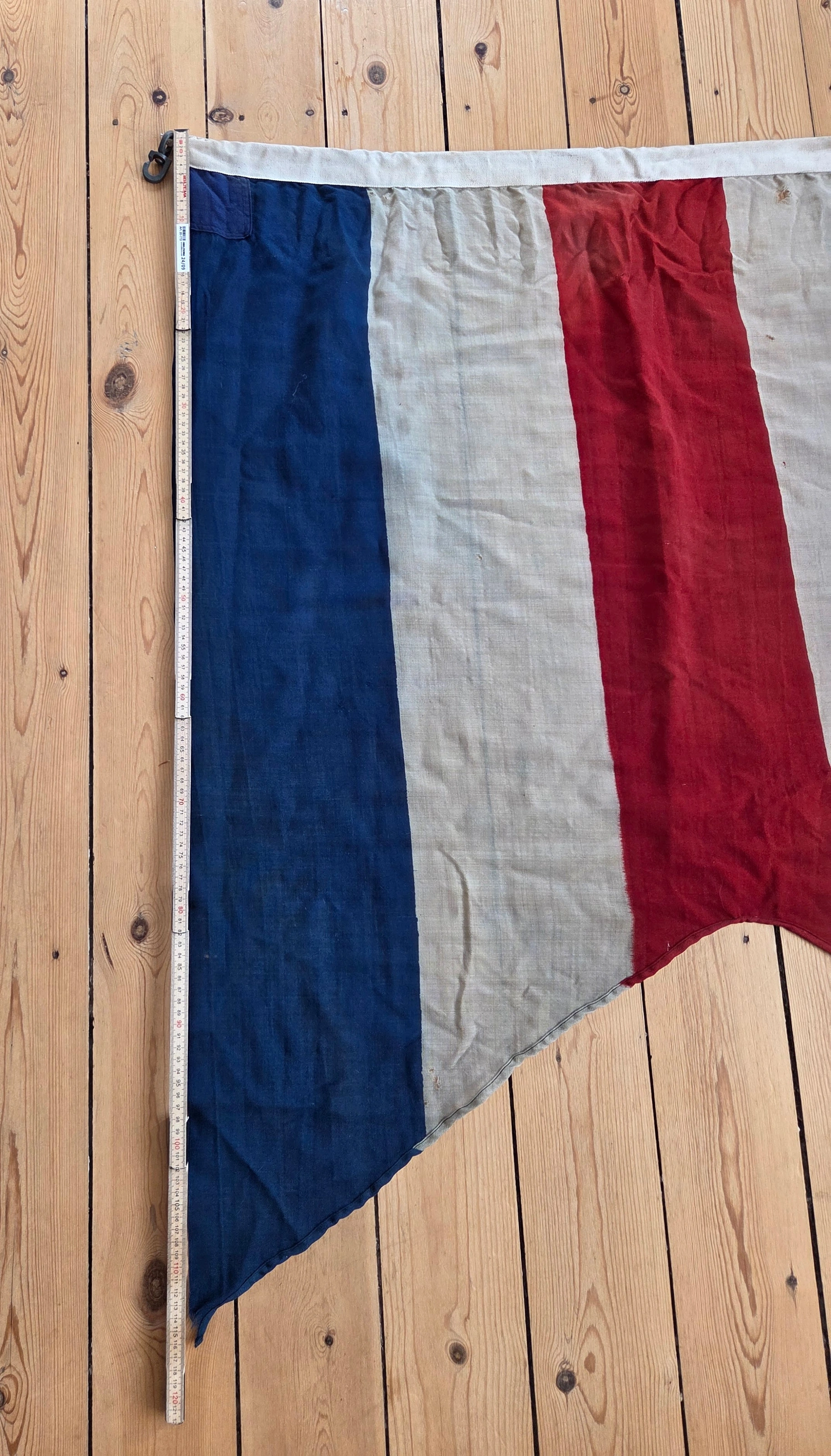
Both surviving examples are stamped Gr. 2 and, as preserved, measure about 93 × 112 cm (FG-047) and 96 × 115 cm (FG-048) to the upper fly corner — i.e. much closer to ≈ 5:6 than to 2:3 or 3:5. Their present sizes are 7–9 % under nominal Gr. 2 (100 × 120 cm), fully consistent with wool-bunting shrinkage, workshop tolerances, and in-service wear.
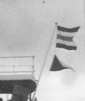
Two independent external examples reinforce this range. The Haus der Geschichte, Bonn specimen measures 114 × 97 cm (outer dimension), again within the Gr. 2 family. Likewise, Thilo Biegler’s published “Gr. 1 C” photograph (FIAV paper 15-11) shows a visually comparable body ratio (≈ 5:6) and a broad, open wedge. Together with our two maker-stamped pieces, the Hansa Greiffenfels photo, and the 1949 film still, the evidence converges on a single working template — a reused signal-flag rectangle.
In both Allied radio order and Law No. 39 there were no centimetre or ratio specifications.
Bridge to 6a. Even though the size and ratio on the six references almost speak for themselves, we ran a photogrammetric check anyway — for completeness. To cross-check the measured cloth reality against a period photograph, we add a photogrammetric estimate from the Greiffenfels stern image. The ship’s railing serves as a ≈ 1.0 m scale reference, based on contemporary yard standards and prior measurements of similar vessels. Using this fixed element, we extract hoist and fly pixel lengths and correct for camera angle and wind billow. The calculation is illustrative rather than normative.
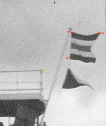
Fig. 6-1: Greiffenfels stern, C-Doppelstander crop (control points as described).
Method (control points)
Let P₀ = upper hoist corner, P₁ = lower hoist corner (defines hoist H = |P₀P₁|).
Let P₂ = upper fly corner at the start of the swallowtail notch (where the upper edge meets the cut).
Measure along the upper edge from P₀ to P₂ to obtain the observed fly length L_obs.
Pixel reads (from the crop)
• Reference railing S (yellow line, ≈ 1.0 m): 83 px
• Hoist H = |P₀P₁| ≈ 91 px
• Observed fly L_obs = |P₀P₂| ≈ 96 px
Observed ratio (no correction)
r_obs = L_obs / H ≈ 96 / 91 ≈ 1.05
Projection and billow corrections
Two effects shorten the apparent fly length:
(i) projection (flag plane yawed to camera) → factor ≈ cos θ;
(ii) wind billow (edge curvature; chord < arc) → factor β (≈ 0.92–0.96 for a moderately drawing ensign).
Correction formula
r_true = r_obs / (cos θ × β)
Conservative bounds
θ ≈ 5–15° → cos θ ≈ 0.996–0.966;
β ≈ 0.92–0.96;
Combined shortening = cos θ × β ≈ 0.956–0.887;
Therefore r_true ∈ [1.05 / 0.956, 1.05 / 0.887] ≈ 1.10–1.18.
Uncertainty
Pixel reads carry ± 2 px; relative to H ≈ 91 px this is ± 2.2 %. Propagated through r_obs and corrections, a conservative envelope is 1.08–1.20. Values depend on control-point placement and the 1 m rail assumption; results are indicative only.
Limitations and intent.
This analysis is illustrative and serves as a visual cross-check rather than a precision survey. The Greiffenfels photo alone shows that the flag’s base rectangle is visibly not 2:3. The computed range (≈ 1.08–1.20) simply quantifies that observation: a reused signal-flag body adapted into a broader-tailed ensign.
Interpretation.
A base-rectangle ratio in the 1.08–1.20 band corresponds closely to 5:6 (1.20) and is well removed from 2:3 (1.50) or 3:5 (1.67). Scaled via the railing (≈ 1.0 m = 83 px), the hoist and observed fly correspond to ≈ 1.10 m and ≈ 1.16 m, respectively. The slightly long hoist and short fly are both consistent with projection and billow effects. After correction, the effective ratio aligns with the known ~5:6 signal-flag family.
Independent check.
A repeat measurement by an independent reviewer using the same crop and method returned hoist ≈ 1.15–1.20 m and fly ≈ 1.22–1.33 m after correction. The resulting ratio again falls within the 5:6 family and well away from 2:3 or 3:5.
The Allied radio order instructed German and ex-German ships to fly the International Code Flag “C” as a burgee — no measurements, no ratio table. Annex A to Allied Control Council Law No. 39 later repeated the instruction schematically but likewise gave no centimetre data or proportional reference.
In practice, this meant that the flag’s body came directly from existing Signal C stock in the standard size families (Gr. 1 ≈ 50×60 cm, Gr. 2 ≈ 100×120 cm, Gr. 3 ≈ 150×180 cm). The directive simply activated what workshops and ships already had on hand.
Six independent reference points support this interpretation: our two maker-stamped examples (FG-047/048), both Gr. 2; Biegler’s documented Gr. 1 piece; the Bonn Museum flag (114 × 97 cm); the Greiffenfels photographs; and the 1949 film still showing the ensign in active use. All cluster tightly around the ~5:6 ratio family rather than 2:3 or 3:5.
This defines the proportions of the flag’s body. The question of the tail geometry is separate: Annex A depicts a schematic wedge, but verified examples show a visibly broader cut. Section 7b examines that divergence in detail.
Even without calculation, the photographs and surviving flags make it clear: none of the observed swallowtails approach the 90° schematic shown in Annex A of Allied Control Council Law No. 39. Every documented example shows a visibly broader cut—typically between 106° and 110°.
Again, just for completeness, we ran a geometric check to visualise the deviation from the theoretical 90° wedge.
We tested three independent sources:
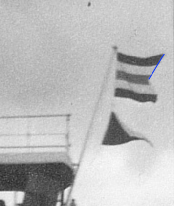
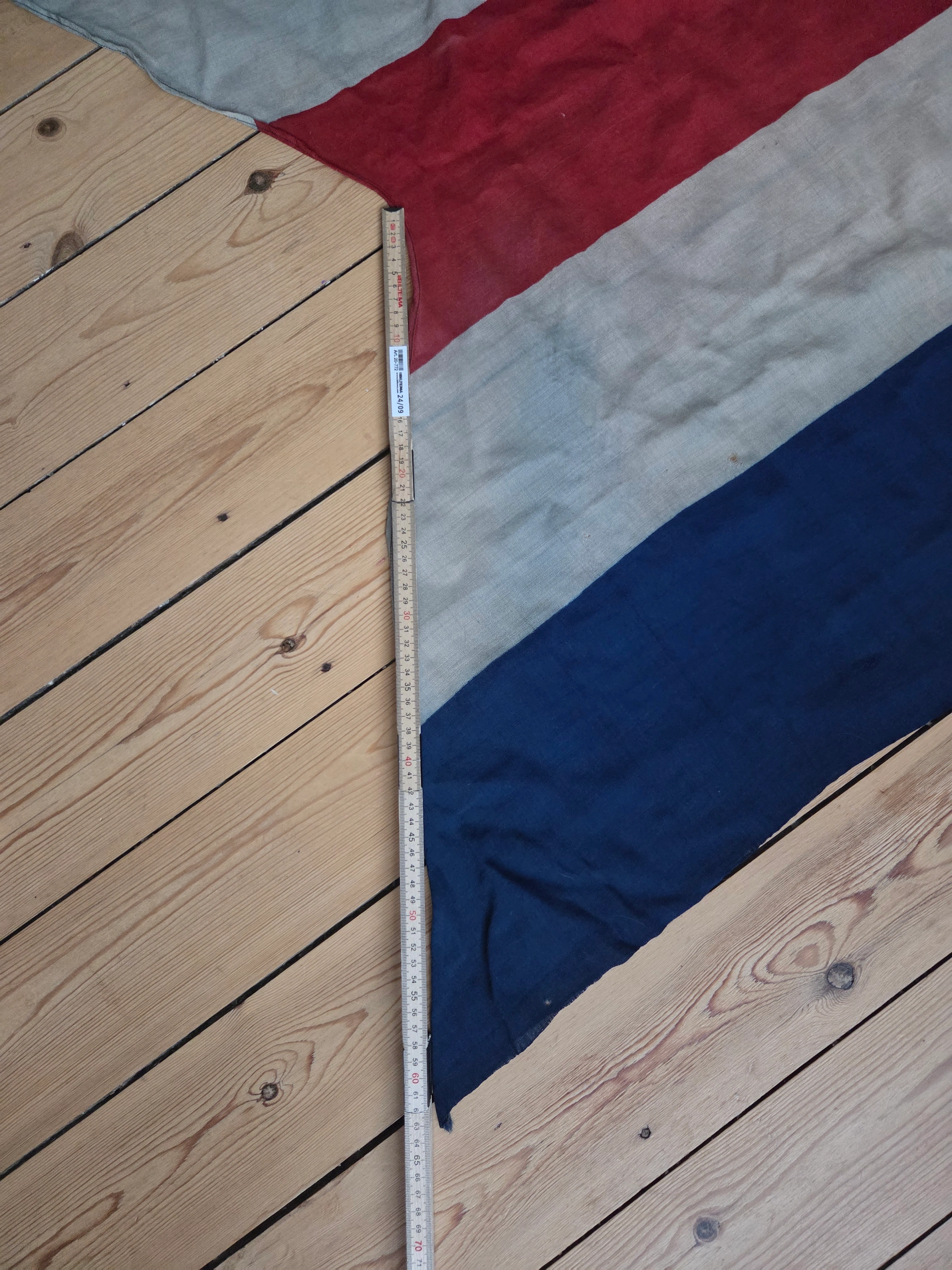
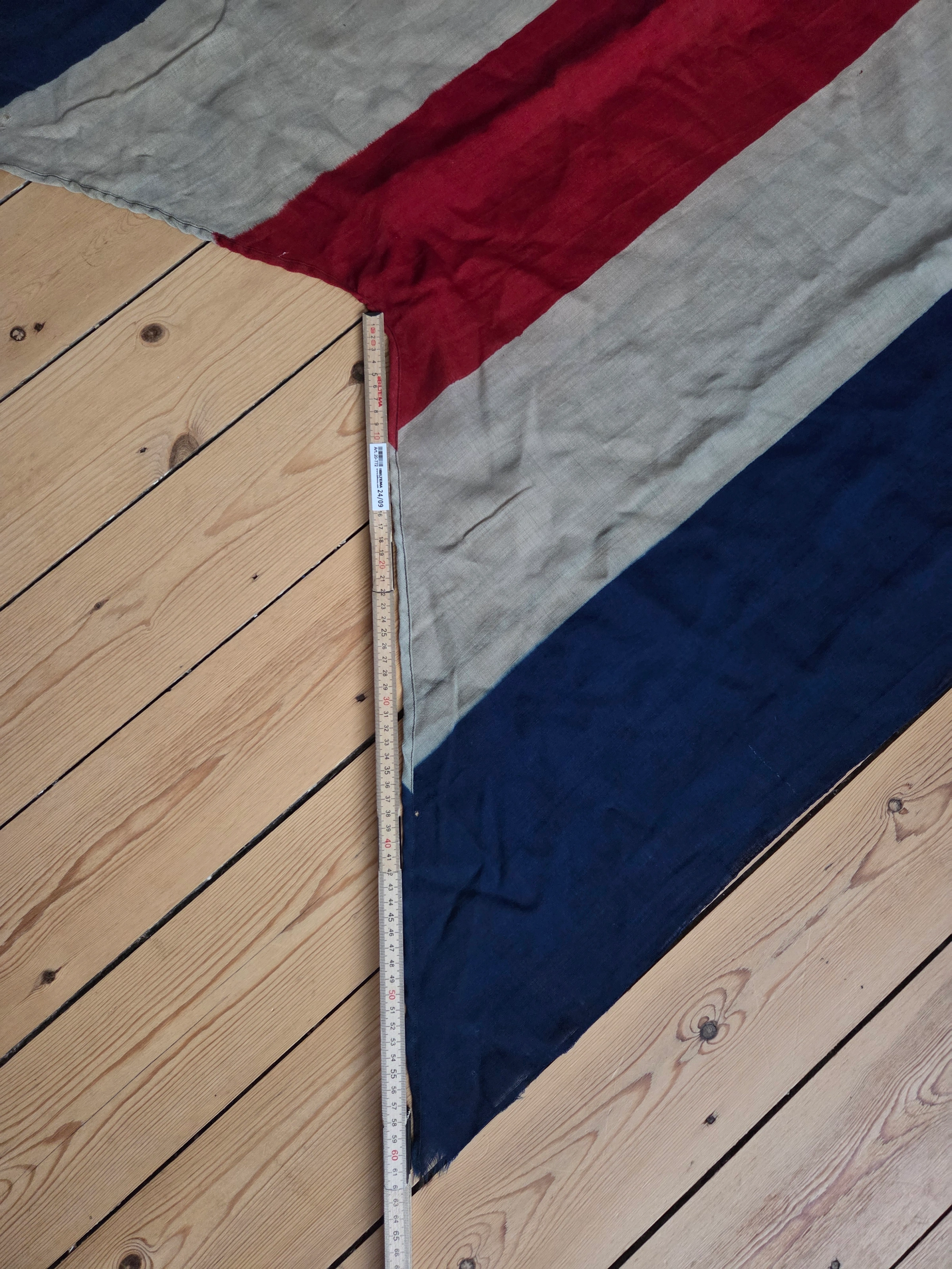
This subsection quantifies what the eye already suggests. Using a single Greiffenfels stern photograph, the goal was not precision engineering but a sanity check — confirming whether the measured wedge aligns with the same ~106–110° pattern observed on both surviving cloth flags.
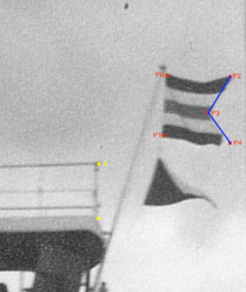
Fig. 7-1: Greiffenfels stern, C-Doppelstander crop (angle control points as described).
Method (control points)
We report the exterior (“wedge”) angle ω at the swallowtail apex.
Let P₀ = upper hoist corner, P₁ = lower hoist corner (defines Hoist H = |P₀P₁|).
Let P₂ = upper notch corner, P₄ = lower notch corner, P₃ = notch apex.
Let d = mean(|P₂P₃|, |P₄P₃|). Compute the wedge directly as:
ω = 180° − 2·atan(d / H).
Pixel reads (from the crop)
• Reference railing (≈1.0 m): 83 px (S, yellow)
• Hoist H ≈ 91 px → ≈ 1.10 m (P₀→P₁)
• Cut-depth legs: 57 px, 55 px → mean d ≈ 56 px (P₂→P₃ and P₃→P₄, blue)
Observed wedge (no correction)
ω_obs = 180° − 2·atan(56 / 91) ≈ 117°
Projection & billow corrections
Perspective and sail-shape billow make the notch appear deeper; this reduces the wedge angle on the photo.
A conservative correction of −7–11° on ω is appropriate.
Therefore
ω_true ≈ 106–110°
Uncertainty
±2 px on d and H (~±2%) propagates directly; a conservative envelope is ~106–113°.
Limitations and intent.
The here is likewise illustrative rather than definitive. The Greiffenfels photograph alone makes it visually clear that the swallowtail is far wider than 90°, regardless of exact pixel math. The numerical estimate simply quantifies that visual reality and should be read as an indicative range, not a blueprint measurement.
Interpretation.
The exterior (wedge) angle on Greiffenfels resolves to ~106–110° (conservatively ~106–113°), matching the two Düsseldorfer samples (≈106–107°). This consistency suggests that workshops followed a pre-existing broad-cut template — a practical continuation of earlier German naval standards rather than a literal 90° regulation. Section 7b explores this continuity further.
Peer review notes
Method: law of cosines on triangle P₂–P₃–P₄, legs 55/57 px, base assumed ≈91 px (≈hoist).
Result: interior angle γ ≈109° raw; adjusted for wind/perspective ≈102–109° (mid ≈105°).
Conclusion: The cut angle at P₃ is approximately 102–109°, closest to 105° under observed conditions.
Observation. Every verified example — our two DFF flags, the Greiffenfels photo, Biegler’s image, and the Bonn reference — shows a broad swallowtail around 106–110°.
Hypothesis. The 9 May 1945 order simply said “fly International Code Flag C as a burgee.” No drawings, no ratios — just a plain signal. Crews and sailmakers did what they always did: cut it by eye, using familiar swallow-tailed patterns already on board. The most likely templates (hypothesis) were the wartime Zeppeliner pennant (see FOTW reference) or the A/B patterns referenced in section 3a — later re-designated as Bravo and possibly Alpha signal flags — all sharing the same broad ~105–110° wedge typical of German signal practice.
Workshop continuity. When civilian suppliers such as Düsseldorfer Fahnenfabrik later produced replacement stock, they simply repeated the form already in use — the same broad tail, not the schematic right angle.
Interpretation. The 90° drawing in Law 39 was a bureaucratic simplification of a design already fixed in practice. By the time it appeared in print, the pattern at sea was long established — practical, visible, and cut from tradition rather than from paper.
Note: No construction sheets have yet surfaced; this remains a working interpretation based on cloth, photographs, and workshop logic. Section 9 will return to what this implies for reconstruction and authenticity.
But how do we know our two flags are authentic? Here are the verifiable facts — physical, archival, and chronological — that together establish their originality and period manufacture.
Synthesis. Overlaying construction, maker chronology, and service window leaves a single plausible interval of manufacture: a Düsseldorfer Fahnenfabrik-stamped C-Doppelstander could only have been produced during the immediate post-war occupation period — from the May 1945 order through the 1951 repeal. No later production pathway exists, supporting these as authentic, period-made working flags.
Separate correspondence with the former British owner’s family confirms that both flags were obtained from post-war Army Surplus stock in East London and used to decorate a public house for the 1953 Coronation. The description — “British supply, made in Germany for the Germans; probably never used” — aligns precisely with the known Allied surplus trade of the late 1940s and early 1950s. This account provides independent confirmation that Düsseldorfer Fahnenfabrik occupation flags circulated in civilian hands by the early 1950s, consistent with the workshop’s closure window.
“My family have run pubs in East London for over 100 years... This flag came from one of those stores — probably never used. It was bought before 1953 to decorate a pub for the Queen’s Coronation. Though not a British flag, anything red, white and blue will do.”
— Peter, former pub owner (London), personal correspondence, 2025
The precise route by which these flags reached the United Kingdom remains unknown, as does the specific vessel or depot from which they originated.
Materials control (lead-in to section 8a). To rule out a later conversion of a square signal flag C into a C-Doppelstander, a fibre burn test was performed on the exposed black stitching thread of FG-048’s swallowtail; results follow in section 8a.
Purpose. To demonstrate that the swallowtail cut and its stitching are period-executed (late-1940s/early-1950s) rather than a later conversion of a 1930s–40s stock signal flag “C” (or a modern repair). Synthetic threads (polyester/nylon) melt and bead; period natural fibres ash.
Sample. Single strand taken from the black stitching thread visible in the macro close-up at the frayed swallowtail edge of FG-048.
Method. Handheld flame; behaviour noted before ignition, during burning, and at residue.
Follow the sequence: 1 → 2 → 3 → 4 → 5
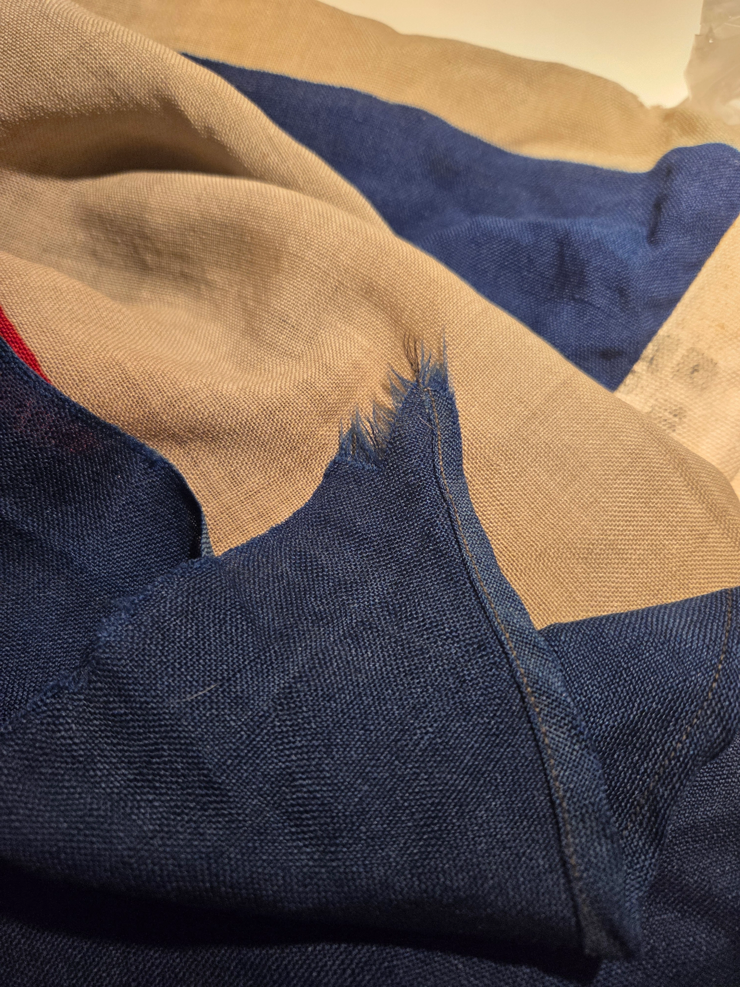
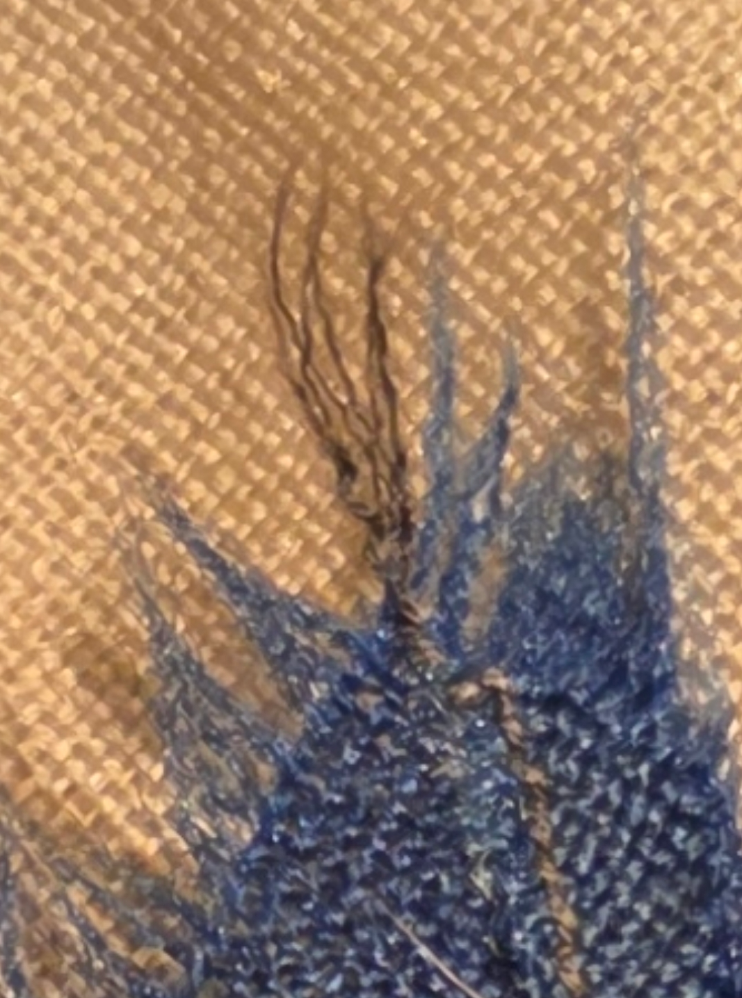
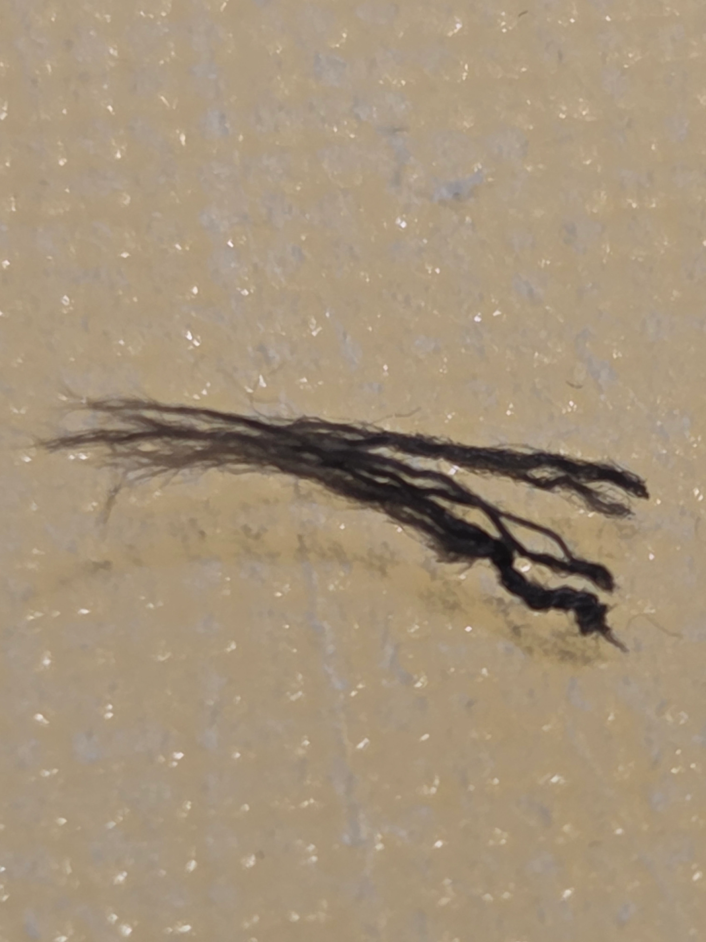
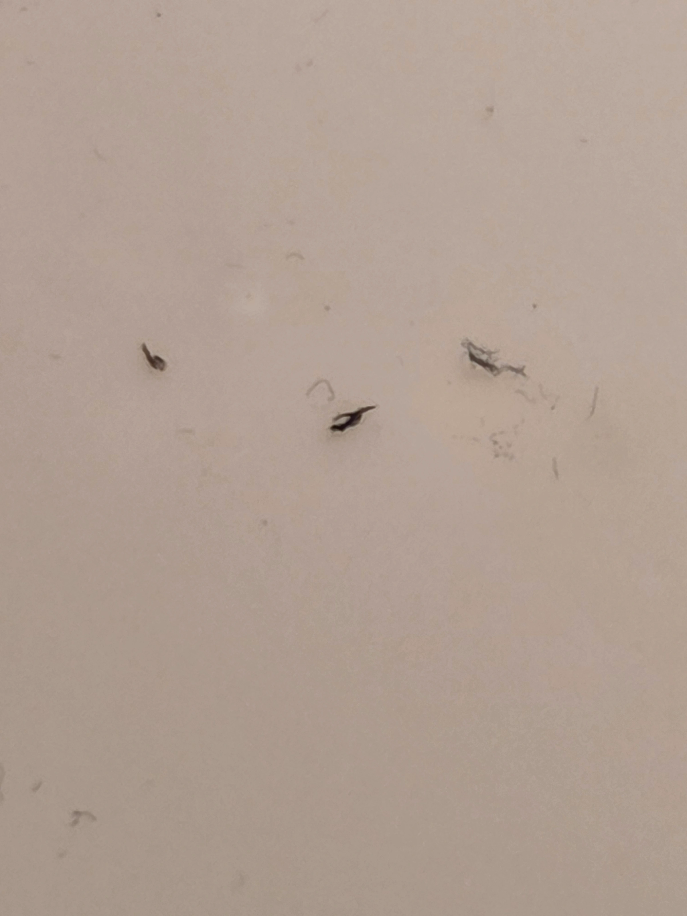
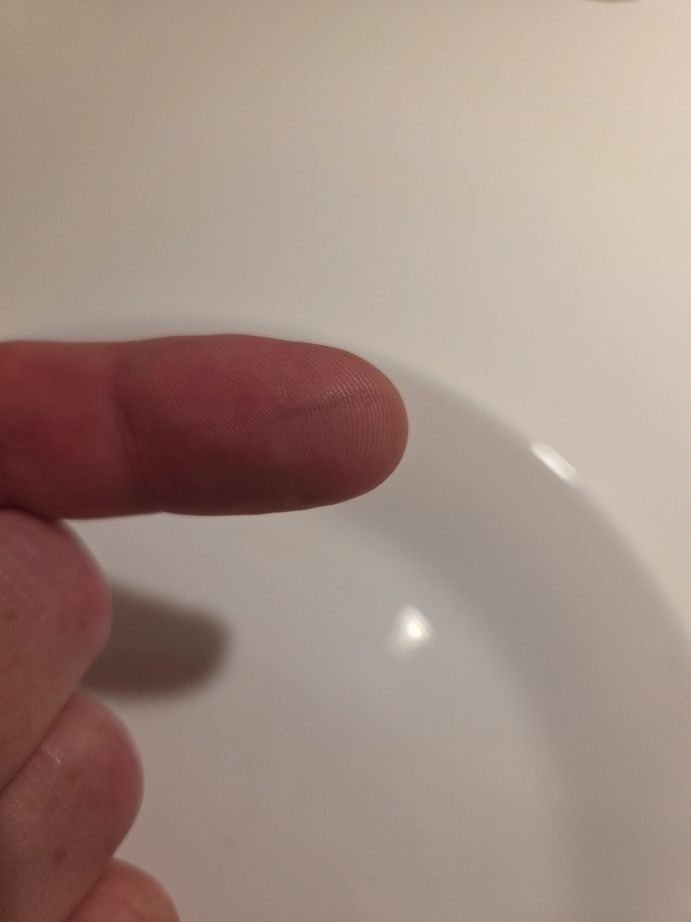
Limitations. Field test only; microscopy/FTIR would discriminate wool vs. cotton definitively. For our purpose—screening for modern synthetics—the result is decisive.
Conclusion. The black swallowtail thread on FG-048 behaves as a period natural-fibre thread (consistent with wool) and does not show synthetic signatures, arguing against a later conversion of an ordinary signal flag “C” into a C-Doppelstander.
Supplementary note (provenance cross-check). A follow-up exchange with the former owner in 2025 further supports the integrity of the flags’ original shape. When asked whether the flags had ever been modified, he replied that he had “only ever known them as swallow-tailed” and had “no reason to think they were ever altered.” This recollection aligns with the physical and material evidence that the triangular cut was executed in-period, not added later for decoration.
(1) Authenticity. Both flags are confirmed period-made. Their Düsseldorfer Fahnenfabrik stamps, materials, thread types, and construction details align perfectly with verified late-1940s practice. Each parameter — maker, markings, fibre, geometry — matches the four external references (Bonn, Biegler, Greiffenfels, and film stills). Together they form a coherent six-point dataset confirming genuine, working C-Doppelstander ensigns.
(2) Ratio and size. All six reference points cluster near 5:6; no evidence supports 2:3 or 3:5. Both the 9 May 1945 war diary and Law No. 39 confirm the use of signal C as the base form, with Annex A adding only a schematic sketch. The right-angle shown there appears purely illustrative — no surviving flag or photo matches it.
(3) Origin and manufacture. Workshops and ship crews followed the 9 May 1945 instruction literally: fly a signal C burgee. They simply cut existing signal-flag stock to the familiar swallow-tail used on wartime pennants (Zeppeliner/Alpha/Bravo). Later production by DFF followed the same logic, yielding the same broad ≈ 106–110° wedge.
(4) Why “C” — and the link to D / E. Archival leads suggest that Signal C was already used during 1943 as an Allied control identifier hoisted below national ensigns, and was later reused by Germany after the surrender as a standalone modified ensign. This also served a symbolic purpose — adopting a neutral signal flag rather than any national design with Nazi associations. Law No. 39 justified the swallowtail form “to avoid confusion” with the square signal, fully consistent with this reuse. The C-based configuration therefore became the working template for the later D (Ryukyu) and E (Japan) occupation flags.
Despite popular claims, there is no evidence that the “C” stood for “Control,” or that its colours were intended to represent Allied forces or national ensigns. Both notions remain unsubstantiated by any primary source or regulation.
In summary: The C-Doppelstander was a practical, workshop-made ensign — ratio ≈ 5 : 6, wedge ≈ 106–110°, signal-flag materials — created directly from existing stock under the 9 May 1945 order and maintained until 1951. Based on archival findings, it is clear that when U.S. and British forces took control over enemy territories, they routinely employed reconstructed International Code of Signals flags as neutral merchant ensigns in place of banned national flags. This practice explains both the reused signal-flag proportions (≈ 5 : 6) and the absence of any verified 2 : 3 or 3 : 5 variants. No confirmed examples show a strict 90° cut, reinforcing that the surviving flags represent the real, working form.
This study also sets the stage for a forthcoming paper exploring the broader Allied use of signal flags — tracing how the A, B, C, D, E (and possibly F) swallow-tail series evolved from wartime communication standards into post-surrender control and identification flags across multiple occupation zones. The next phase will ask whether this sequential system was coincidence, field improvisation, or a deliberate Allied framework.
Note: Click the sections below to expand and view the full image sets.
Historical photographs from the former DDG Hansa photographic archive, reproduced in this article under prior permission.
Cropped views and analytical extracts from these photographs also appear in Sections 6, 6a, 7, and 7a. These derivative images are reproduced solely within the scope of this article.
© 2026–2026 FlagGeek / Kenny Ytrup – Original FlagGeek text, drawings, and analysis are licensed under CC BY-NC 4.0.
Non-commercial sharing with attribution is permitted. Commercial use requires permission.
Third-party photographs are not covered by the CC licence and remain subject to the rights and permissions applicable to each image.
The DDG Hansa historical photographs and all crops or analytical extracts derived from them are reproduced solely within the scope of this article and may not be copied, republished, redistributed, or used elsewhere without separate permission.
Published:
Updated:
Original FlagGeek publication · Source status: LIVE. Research text and evidence retained from the Blogger export.
FlagGeek · https://flaggeek-v2.pages.dev/archive/c-doppelstander/
